Dell Force10 S4820T Getting Started Guide
Dell Force10 S4820T Manual
 |
View all Dell Force10 S4820T manuals
Add to My Manuals
Save this manual to your list of manuals |
Dell Force10 S4820T manual content summary:
- Dell Force10 S4820T | Getting Started Guide - Page 1
Dell Force10 S4820T System Getting Started Guide Publication Date: December 2012 Regulatory Model: S4820T - Dell Force10 S4820T | Getting Started Guide - Page 2
instructions. WARNING: A WARNING indicates a potential for property damage, personal injury, or death. If you purchased a Dell notice. © 2012 Dell Inc. All rights Dell Inc. is strictly forbidden. Trademarks used in this text: Dell™, the DELL logo, Dell Dell Inc. disclaims any proprietary interest in trademarks - Dell Force10 S4820T | Getting Started Guide - Page 3
11 Package Contents 11 Unpacking Steps 11 Power Supplies 12 Install an AC or DC Power Supply 13 Rack Mounting the Switch 14 Rack Mounting Safety Considerations 14 Installing the Dell ReadyRails System 15 Installing the Switch 19 5 Technical Specifications 21 Chassis Physical Design 21 - Dell Force10 S4820T | Getting Started Guide - Page 4
28 Configure the Management Port IP Address 28 Configure the Management Route 29 Configure the Username and Password 29 Configure the Enable Password 29 Create a Port-based VLAN 30 Assign Interfaces to a VLAN 30 Assign an IP Address to a VLAN 32 Connecting the S4820T to the Network 32 - Dell Force10 S4820T | Getting Started Guide - Page 5
Contents Contents 3 - Dell Force10 S4820T | Getting Started Guide - Page 6
Contents 4 Contents - Dell Force10 S4820T | Getting Started Guide - Page 7
Documents Information Hardware installation and power-up instructions Software configuration Command line interface Latest updates Documentation Installing the S4820T System FTOS Configuration Guide for the S4820T System FTOS Command Line Reference Guide for the S4820T System FTOS Release Notes for - Dell Force10 S4820T | Getting Started Guide - Page 8
2 About this Guide - Dell Force10 S4820T | Getting Started Guide - Page 9
ports of 10GBase-T and four ports of 40Gbps with features and functions similar to the S4810 product. The S4820T switch runs the Dell Force10 Operating System (FTOS), providing switching, bridging, and routing functionality for transmitting data, storage, and server traffic. In a data center network - Dell Force10 S4820T | Getting Started Guide - Page 10
The S4820T solution is optimized to provide 10Gbps throughput for distances of up to: • 330 feet (100 meters) over Cat6, 6A, and 7 shielded copper cable and Cat6A UTP copper cable • 181.5 feet (55 meters) over Cat6 UTP copper cable 4 Introduction - Dell Force10 S4820T | Getting Started Guide - Page 11
640Gbps switching bandwidth as listed below: • S4820T = 48 port 10GBase-T + 4 port 40G QSFP+ The system also provides one RS-232 interface RJ-45 YOST console port and a dedicated Ethernet service port for out-of-band (OOB) management functions. The S4820T has the following features: • Supports one - Dell Force10 S4820T | Getting Started Guide - Page 12
Fans The S4820T has stock keeping units (SKUs) that support the following configurations. Installation of the fans is done as part of the factory install based on SKU type. The power supply units (PSUs) are to be installed at the customer site (refer to Power Supplies). • AC PSU with fan airflow - Dell Force10 S4820T | Getting Started Guide - Page 13
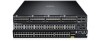
the S4820T front panel. Figure 1-2. S4820T Front Panel 10GBase-T Ports USB 2.0 Port QSFP+ Ports The front panel includes: • 48 fixed 10GBase-T and four fixed QSFP+ ports • One USB 2.0 port NOTE: The light emitting diodes (LEDs) display for System is on the front panel. The fan and power status - Dell Force10 S4820T | Getting Started Guide - Page 14
view status information through the command line interface (CLI) show commands and with simple network management protocol (SNMP). For more information about these options, refer to the FTOS Command Line Reference Guide and FTOS Configuration Guide for the S4820T System. As shown in Figure 1-3, the - Dell Force10 S4820T | Getting Started Guide - Page 15
the S4820T system. supply fail) • Off: Normal temperature PSU side • Solid red -Overtemp (Refer NOTE:) • Off -Normal operating PSU side • Solid green -System Booting or Diagnostics • Solid green -fan powered PSU side and running at the expected rpm • Solid red -fan failed • Solid blue -Switch - Dell Force10 S4820T | Getting Started Guide - Page 16
Link • Blinking green - Transmit/Receive is active Table 1-2. QSFP+ Port LEDs Feature Detailed Description Link LED • Off - No Link • Solid Link • Blinking green - Transmit/Receive is active Table 1-3. OOB Ethernet Port LEDs Feature Detailed Description Link LED • Off - No Link • Solid - Dell Force10 S4820T | Getting Started Guide - Page 17
items are included: • One S4820T switch • One RJ-45 to DB-9 female cable • Two sets of rail kits (no tools required) • One PSU • One AC power cord (country/region specific) • Getting Started Guide • Safety and Regulatory Information • Warranty and Support Information • Software License Agreement - Dell Force10 S4820T | Getting Started Guide - Page 18
S4820T supports AC and DC power supplies with two air-flow directions (I/O to PSU and PSU to I/O). Two PSUs are required for full redundancy, but the system will operate with a single PSU. NOTE: If you use a single PSU, you must install a blank plate in the other PSU slot. Dell Force10 recommends - Dell Force10 S4820T | Getting Started Guide - Page 19
use a single PSU, you must install a blank plate in the other PSU slot. Dell Force10 recommends using power supply 1 (PSU1) as the blank plate slot. Step Task 1 Remove the PSU slot cover from the S4820T (PSU side of switch), either of the two PSU slots may be selected. 2 Remove the PSU from the - Dell Force10 S4820T | Getting Started Guide - Page 20
). The Dell ReadyRails™ system is provided for 1U front-rack, and two-post installations. The ReadyRails system includes two separately packaged rail assemblies and two rails that are shipped attached to the sides of the switch. WARNING: This is a condensed reference. Read the safety instructions in - Dell Force10 S4820T | Getting Started Guide - Page 21
Installing the Dell ReadyRails System The ReadyRails rack mounting system is provided to easily configure your rack for installation of your switch. The ReadyRails system can be installed using the 1U tool-less method or one of three possible 1U tooled methods (two-post flush mount, two- - Dell Force10 S4820T | Getting Started Guide - Page 22
ear (on the switch side of the rail) and remove each casting. Retain the castings for future rack requirements. It is not necessary to remove the rear flange castings. Figure 1-6. Two-post Flush-mount Configuration 2 Attach one rail to the front post flange with two user-supplied screws. Refer to - Dell Force10 S4820T | Getting Started Guide - Page 23
plunger bracket rearward until it clicks into place and secure the bracket to the front post flange with two user-supplied screws. Refer to Figure 1-7, item 1. Figure 1-7. Two-post Center-mount Configuration 2 Slide the back bracket towards the post and secure it to the post flange with two user - Dell Force10 S4820T | Getting Started Guide - Page 24
Four-post Threaded Configuration: 1 For this configuration, you must remove the flange ear castings from each end of the ReadyRails each rail, attach the front and rear flanges to the post flanges with two user-supplied screws at each end. Refer to Figure 1-8, item 2. Figure 1-8. Four-post Threaded - Dell Force10 S4820T | Getting Started Guide - Page 25
into the rails in the same manner as the four-post configurations. 1U Front-rack Installation You must configure the rails that are attached to the switch. 1 Attach the switch rails (inner chassis members) to the S4820T switch. Figure 1-9, item 1 shows the detail for the front standoff with the - Dell Force10 S4820T | Getting Started Guide - Page 26
are installed, line them up on the previously mounted Ready-Rails and slide the switch in until it is flush with front of rack. About three inches prior to full insertion, the rail locking feature engages to keep the switch from inadvertently sliding out of the rack and falling. 20 Installation - Dell Force10 S4820T | Getting Started Guide - Page 27
or equivalent type. Dispose of the batteries according to the manufacturer's instructions. Chassis Physical Design Parameter Height Width Depth Specifications 1.71 inches ( humidity Maximum thermal output Specifications 32° to 104°F (0° to 40°C) 10 to 85% (RH), non-condensing -40° to 158°F (-40° - Dell Force10 S4820T | Getting Started Guide - Page 28
/200vac 398.02 Watts MTBF 355,178 hours NOTE: The table below represents the DC PSU's capabilities and does not represent the S4820T operation. DC Input Specification The power supply operates within all specified limits over the following input voltage range. min/max input voltage range input - Dell Force10 S4820T | Getting Started Guide - Page 29
IEEE Standards The S4820T switch complies with the following IEEE standards: •802.1AB LLDP •802.1ag Connectivity fault Management •802.1D Aggregation with LACP •802.3ae 10 Gigabit Ethernet (10GBASE-X) •802.3ba 40 Gigabit Ethernet (40GBase-SR4, 40GBase-CR4) on optical ports •802.3u Fast Ethernet - Dell Force10 S4820T | Getting Started Guide - Page 30
24 Technical Specifications - Dell Force10 S4820T | Getting Started Guide - Page 31
2 Performing the Initial Configuration Navigating CLI Modes The FTOS prompt changes to indicate emulation program already installed on your PC. The RS-232/RJ-45 console port is labeled on the upper right-hand side of the S4820T system as you face the Input/Output (I/O) side of the chassis (Figure - Dell Force10 S4820T | Getting Started Guide - Page 32
45 copper cable into the console port. Use a rollover cable to connect the S4820T console port to a terminal server. 2 flow control Accessing the RJ-45 Console Port with a DB-9 Adapter If the DTE has a DB-9 interface, you can connect to the console using RTS 26 Performing the Initial Configuration - Dell Force10 S4820T | Getting Started Guide - Page 33
-loaded onto the S4820T system; however, the system is not configured when you power up for the first time (except for the default host name, which is FTOS). You must configure the system using the CLI. Configure Layer 2 (Data Link) Mode Use the switchport command in INTERFACE mode to enable Layer - Dell Force10 S4820T | Getting Started Guide - Page 34
remotely, assign IP addresses to the management ports. To assign IP addresses to the management ports, follow these steps: Step Task Command Syntax Command Mode 1 Enter INTERFACE interface ManagementEthernet CONFIGURATION mode for the slot/port Management port. 2 Assign an IP address ip - Dell Force10 S4820T | Getting Started Guide - Page 35
you are accessing the S4820T remotely. Management routes are separate from IP routes and are used to manage the S4820T through the management port. To configure a management route, follow this step: Task Command Syntax Command Mode Configure a management route to the network from which you are - Dell Force10 S4820T | Getting Started Guide - Page 36
based VLAN, you must create the VLAN and then add physical interfaces or port channel (LAG) interfaces to the VLAN. To create a port-based VLAN, follow this step: Task Command Syntax Command Mode Configure a port-based VLAN (if the interface vlan vlan-id vlan-id is different from the Default VLAN - Dell Force10 S4820T | Getting Started Guide - Page 37
port-based VLAN to tag it with that VLAN ID. To tag interfaces, follow these steps: Step Task Command Syntax Command Mode 1 Access the interface vlan vlan-id INTERFACE VLAN mode of the VLAN to which you want to assign the interface. CONFIGURATION 2 Enable an interface to tagged interface - Dell Force10 S4820T | Getting Started Guide - Page 38
ip-address mask and mask on the interface. [secondary] INTERFACE Connecting the S4820T to the Network After you have completed the hardware installation and software configuration for the S4820T system, you can connect to your company network by following your company's cabling requirements. 32 - Dell Force10 S4820T | Getting Started Guide - Page 39
Printed in the U.S.A. www.dell.com | support.dell.com
-
 1
1 -
 2
2 -
 3
3 -
 4
4 -
 5
5 -
 6
6 -
 7
7 -
8
-
9
-
10
-
11
-
12
-
13
-
14
-
15
-
16
-
17
-
18
-
19
-
20
-
21
-
22
-
23
-
24
-
25
-
26
-
27
-
28
-
29
-
30
-
31
-
32
-
33
-
34
-
35
-
36
-
37
-
38
-
39
 |
 |

Dell Force10
S4820T System
Getting Started Guide
Publication Date: December 2012
Regulatory Model: S4820T