Dell Force10 S4820T Getting Started Guide - Page 21
Installing the Dell ReadyRails System
 |
View all Dell Force10 S4820T manuals
Add to My Manuals
Save this manual to your list of manuals |
Page 21 highlights
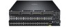
Installing the Dell ReadyRails System The ReadyRails rack mounting system is provided to easily configure your rack for installation of your switch. The ReadyRails system can be installed using the 1U tool-less method or one of three possible 1U tooled methods (two-post flush mount, two-post center mount, or four-post threaded). 1U Tool-less Configuration (Four-post Square Hole or Unthreaded Round Hole): 1 With the ReadyRails flange ears facing outward, place one rail between the left and right vertical posts. Align and seat the rear flange rail pegs in the rear vertical post flange. In Figure 1-5, item 1 and its extractions show how the pegs appear in both the square and unthreaded round holes. Figure 1-5. 1U Tool-less Configuration 2 Align and seat the front flange pegs in the holes on the front side of the vertical post. Refer to Figure 1-5, item 2. 3 Repeat this procedure for the second rail. 4 To remove each rail, pull on the latch release button on each flange ear and unseat each rail. Refer to Figure 1-5, item 3. Installation 15
-
 1
1 -
2
-
3
-
4
-
5
-
6
-
7
-
8
-
9
-
10
-
11
-
12
-
13
-
14
-
15
-
 16
16 -
 17
17 -
 18
18 -
 19
19 -
 20
20 -
 21
21 -
 22
22 -
 23
23 -
 24
24 -
 25
25 -
 26
26 -
27
-
28
-
29
-
30
-
31
-
32
-
33
-
34
-
35
-
36
-
37
-
38
-
39
 |
 |
