Dell Inspiron 13 7375 2-in-1 Inspiron 13 7000 2-in-1 Service Manual
Dell Inspiron 13 7375 2-in-1 Manual
 |
View all Dell Inspiron 13 7375 2-in-1 manuals
Add to My Manuals
Save this manual to your list of manuals |
Dell Inspiron 13 7375 2-in-1 manual content summary:
- Dell Inspiron 13 7375 2-in-1 | Inspiron 13 7000 2-in-1 Service Manual - Page 1
Inspiron 13 7000 2-in-1 Service Manual Computer Model: Inspiron 13-7375 Regulatory Model: P69G Regulatory Type: P69G002 - Dell Inspiron 13 7375 2-in-1 | Inspiron 13 7000 2-in-1 Service Manual - Page 2
use of your product. CAUTION: A CAUTION indicates either potential damage to hardware or loss of data and tells you how to avoid the problem. WARNING: A WARNING indicates a potential for property damage, personal injury, or death. © 2018 Dell Inc. or its subsidiaries. All rights reserved. Dell, EMC - Dell Inspiron 13 7375 2-in-1 | Inspiron 13 7000 2-in-1 Service Manual - Page 3
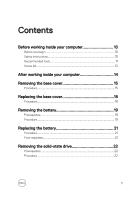
Contents Before working inside your computer 10 Before you begin 10 Safety instructions 10 Recommended tools 11 Screw list 12 After working inside your computer 14 Removing the base cover 15 Procedure 15 Replacing the base cover 18 - Dell Inspiron 13 7375 2-in-1 | Inspiron 13 7000 2-in-1 Service Manual - Page 4
Replacing the solid-state drive 24 Procedure 24 Post-requisites 25 Removing the memory modules 26 Prerequisites 26 Procedure 27 Replacing the memory modules 29 Procedure 29 Post-requisites 31 Removing the coin-cell battery 32 Prerequisites 32 Procedure 32 Replacing the coin-cell battery - Dell Inspiron 13 7375 2-in-1 | Inspiron 13 7000 2-in-1 Service Manual - Page 5
Replacing the speakers 41 Procedure 41 Post-requisites 41 Removing the fan 42 Prerequisites 42 Procedure 42 Replacing the fan 44 Procedure 44 Post-requisites 44 Removing the heat sink 45 Prerequisites 45 Procedure 45 Replacing the heat sink 47 Procedure 47 Post-requisites 47 Removing - Dell Inspiron 13 7375 2-in-1 | Inspiron 13 7000 2-in-1 Service Manual - Page 6
Replacing the power and volume-buttons board.......... 53 Procedure 53 Post-requisites 53 Removing the status-light board 54 Prerequisites 54 Procedure 54 Replacing the status-light board 56 Procedure 56 Post-requisites 56 Removing the touchpad 57 Prerequisites 57 Procedure 57 Replacing - Dell Inspiron 13 7375 2-in-1 | Inspiron 13 7000 2-in-1 Service Manual - Page 7
requisites 68 Removing the system board 69 Prerequisites 69 Procedure 69 Replacing the system board 74 Procedure 74 Post-requisites 75 Entering the Service Tag in the BIOS setup program 75 Removing the keyboard 76 Prerequisites 76 Procedure 77 Replacing the keyboard 80 Procedure 80 Post - Dell Inspiron 13 7375 2-in-1 | Inspiron 13 7000 2-in-1 Service Manual - Page 8
Replacing the display panel 89 Procedure 89 Post-requisites 89 Removing the display back-cover and antenna assembly 90 Prerequisites 90 Procedure 90 Replacing the display back-cover and antenna assembly 92 Procedure 92 Post-requisites 92 Removing the camera 93 Prerequisites 93 Procedure - Dell Inspiron 13 7375 2-in-1 | Inspiron 13 7000 2-in-1 Service Manual - Page 9
setup 104 Boot Sequence 104 Navigation keys 104 BIOS overview 105 Entering the BIOS setup program 105 System setup options 105 Troubleshooting 112 Flashing the BIOS 112 Enhanced Pre-Boot System Assessment (ePSA) diagnostics 112 Running the ePSA diagnostics 113 System diagnostic lights - Dell Inspiron 13 7375 2-in-1 | Inspiron 13 7000 2-in-1 Service Manual - Page 10
as keyboard, mouse, and monitor from your computer. 5 Remove any media card and optical disc from your computer, if applicable. Safety instructions Use the following safety guidelines to protect your computer from potential damage and ensure your personal safety. WARNING: Before working inside your - Dell Inspiron 13 7375 2-in-1 | Inspiron 13 7000 2-in-1 Service Manual - Page 11
pins and contacts. CAUTION: You should only perform troubleshooting and repairs as authorized or directed by the Dell technical assistance team. Damage due to servicing that is not authorized by Dell is not covered by your warranty. See the safety instructions that shipped with the product or at www - Dell Inspiron 13 7375 2-in-1 | Inspiron 13 7000 2-in-1 Service Manual - Page 12
Screw list The following table provides the list of screws that are used for securing different components to the computer. Table 1. Screw list Component Secured to Screw type Quantity Base cover Palm-rest M2.5x7 9 assembly Battery Palm-rest assembly Solid-state drive Palm-rest assembly - Dell Inspiron 13 7375 2-in-1 | Inspiron 13 7000 2-in-1 Service Manual - Page 13
Component System board bracket System board Keyboard shield Keyboard Sensor board Secured to System board and palm-rest assembly Palm-rest assembly Palm-rest assembly Palm-rest assembly Display panel Screw type M2.5x5 Quantity 2 M2x2 Big Head 3 M2x2 Big Head 14 M1.2xL1.4 14 M2.5x2.5 Big 1 - Dell Inspiron 13 7375 2-in-1 | Inspiron 13 7000 2-in-1 Service Manual - Page 14
After working inside your computer CAUTION: Leaving stray or loose screws inside your computer may severely damage your computer. 1 Replace all screws and ensure that no stray screws remain inside your computer. 2 Connect any external devices, peripherals, or cables you removed before working on - Dell Inspiron 13 7375 2-in-1 | Inspiron 13 7000 2-in-1 Service Manual - Page 15
shipped with your computer and follow the steps in Before working inside your computer. After working inside your computer, follow the instructions in After working inside your computer. For more safety best practices, see the Regulatory Compliance home page at www.dell.com/ regulatory_compliance - Dell Inspiron 13 7375 2-in-1 | Inspiron 13 7000 2-in-1 Service Manual - Page 16
2 Remove the nine screws (M2.5x7) that secure the base cover to the palm-rest assembly. Figure 1. Removing the screws 1 screws (9) 3 palm-rest assembly 2 base cover 16 - Dell Inspiron 13 7375 2-in-1 | Inspiron 13 7000 2-in-1 Service Manual - Page 17
3 Using a plastic scribe, release the tabs that secure the base cover to the palmrest assembly and remove the base cover off the palm-rest assembly. Figure 2. Removing the base cover 1 plastic scribe 3 base cover 2 palm-rest assembly 17 - Dell Inspiron 13 7375 2-in-1 | Inspiron 13 7000 2-in-1 Service Manual - Page 18
shipped with your computer and follow the steps in Before working inside your computer. After working inside your computer, follow the instructions in After working inside your computer. For more safety best practices, see the Regulatory Compliance home page at www.dell.com/ regulatory_compliance - Dell Inspiron 13 7375 2-in-1 | Inspiron 13 7000 2-in-1 Service Manual - Page 19
shipped with your computer and follow the steps in Before working inside your computer. After working inside your computer, follow the instructions in After working inside your computer. For more safety best practices, see the Regulatory Compliance home page at www.dell.com/ regulatory_compliance - Dell Inspiron 13 7375 2-in-1 | Inspiron 13 7000 2-in-1 Service Manual - Page 20
3 Lift the battery off the palm-rest assembly. Figure 3. Removing the battery 1 system board 3 screws (4) 5 battery 2 battery cable 4 palm-rest assembly 4 Press and hold the power button for five seconds to ground the system board. 20 - Dell Inspiron 13 7375 2-in-1 | Inspiron 13 7000 2-in-1 Service Manual - Page 21
shipped with your computer and follow the steps in Before working inside your computer. After working inside your computer, follow the instructions in After working inside your computer. For more safety best practices, see the Regulatory Compliance home page at www.dell.com/ regulatory_compliance - Dell Inspiron 13 7375 2-in-1 | Inspiron 13 7000 2-in-1 Service Manual - Page 22
shipped with your computer and follow the steps in Before working inside your computer. After working inside your computer, follow the instructions in After working inside your computer. For more safety best practices, see the Regulatory Compliance home page at www.dell.com/ regulatory_compliance - Dell Inspiron 13 7375 2-in-1 | Inspiron 13 7000 2-in-1 Service Manual - Page 23
2 Slide and remove the solid-state drive off the system board. Figure 4. Removing the solid-state drive 1 screw 3 solid-state drive slot 5 palm-rest assembly 2 solid-state drive 4 system board 23 - Dell Inspiron 13 7375 2-in-1 | Inspiron 13 7000 2-in-1 Service Manual - Page 24
shipped with your computer and follow the steps in Before working inside your computer. After working inside your computer, follow the instructions in After working inside your computer. For more safety best practices, see the Regulatory Compliance home page at www.dell.com/ regulatory_compliance - Dell Inspiron 13 7375 2-in-1 | Inspiron 13 7000 2-in-1 Service Manual - Page 25
2 Press the other end of the solid-state drive and replace the screw (M2x3) that secures the solid-state drive to the palm-rest assembly. Figure 5. Replacing solid-state drive 1 screw 3 solid-state drive slot 5 palm-rest assembly Post-requisites 1 Replace the battery. 2 Replace the base cover. 2 - Dell Inspiron 13 7375 2-in-1 | Inspiron 13 7000 2-in-1 Service Manual - Page 26
shipped with your computer and follow the steps in Before working inside your computer. After working inside your computer, follow the instructions in After working inside your computer. For more safety best practices, see the Regulatory Compliance home page at www.dell.com/ regulatory_compliance - Dell Inspiron 13 7375 2-in-1 | Inspiron 13 7000 2-in-1 Service Manual - Page 27
Procedure 1 Lift the Mylar to access the memory module. Figure 6. Removing the Mylar 1 memory module 2 Mylar 2 Use your fingertips to carefully spread apart the securing-clips on each end of the memory-module slot until the memory module pops up. 27 - Dell Inspiron 13 7375 2-in-1 | Inspiron 13 7000 2-in-1 Service Manual - Page 28
3 Remove the memory module from the memory-module slot. Figure 7. Removing the memory module 1 securing clips (2) 3 memory-module slot 2 memory module 28 - Dell Inspiron 13 7375 2-in-1 | Inspiron 13 7000 2-in-1 Service Manual - Page 29
shipped with your computer and follow the steps in Before working inside your computer. After working inside your computer, follow the instructions in After working inside your computer. For more safety best practices, see the Regulatory Compliance home page at www.dell.com/ regulatory_compliance - Dell Inspiron 13 7375 2-in-1 | Inspiron 13 7000 2-in-1 Service Manual - Page 30
3 Slide the memory module firmly into the slot at an angle and press the memory module down until it clicks into place. NOTE: If you do not hear the click, remove the memory module and reinstall it. Figure 8. Replacing the memory module 1 memory module 3 notch 5 Mylar 2 memory-module slot 4 tab - Dell Inspiron 13 7375 2-in-1 | Inspiron 13 7000 2-in-1 Service Manual - Page 31
Post-requisites 1 Replace the battery. 2 Replace the base cover. 31 - Dell Inspiron 13 7375 2-in-1 | Inspiron 13 7000 2-in-1 Service Manual - Page 32
shipped with your computer and follow the steps in Before working inside your computer. After working inside your computer, follow the instructions in After working inside your computer. For more safety best practices, see the Regulatory Compliance home page at www.dell.com/ regulatory_compliance - Dell Inspiron 13 7375 2-in-1 | Inspiron 13 7000 2-in-1 Service Manual - Page 33
2 Peel the coin-cell battery off the palm-rest assembly. Figure 9. Removing the coin-cell battery 1 I/O board 3 coin-cell battery 2 coin-cell battery cable 4 palm-rest assembly 33 - Dell Inspiron 13 7375 2-in-1 | Inspiron 13 7000 2-in-1 Service Manual - Page 34
shipped with your computer and follow the steps in Before working inside your computer. After working inside your computer, follow the instructions in After working inside your computer. For more safety best practices, see the Regulatory Compliance home page at www.dell.com/ regulatory_compliance - Dell Inspiron 13 7375 2-in-1 | Inspiron 13 7000 2-in-1 Service Manual - Page 35
shipped with your computer and follow the steps in Before working inside your computer. After working inside your computer, follow the instructions in After working inside your computer. For more safety best practices, see the Regulatory Compliance home page at www.dell.com/ regulatory_compliance - Dell Inspiron 13 7375 2-in-1 | Inspiron 13 7000 2-in-1 Service Manual - Page 36
3 Slide and remove the wireless card from the wireless-card slot. Figure 10. Removing the wireless card 1 screw 3 wireless-card slot 5 antenna cables (2) 2 wireless-card bracket 4 wireless card 36 - Dell Inspiron 13 7375 2-in-1 | Inspiron 13 7000 2-in-1 Service Manual - Page 37
inside your computer. After working inside your computer, follow the instructions in After working inside your computer. For more safety best following table provides the antenna-cable color scheme for the wireless card supported by your computer. Table 2. Antenna-cable color scheme Connectors on - Dell Inspiron 13 7375 2-in-1 | Inspiron 13 7000 2-in-1 Service Manual - Page 38
5 Replace the screw (M2x3) that secures the wireless card bracket to the wireless card. Figure 11. Replacing the wireless card 1 tab 3 wireless-card slot 5 antenna cables (2) 7 screw Post-requisites 1 Replace the battery. 2 Replace the base cover. 2 notch 4 wireless card 6 wireless card bracket - Dell Inspiron 13 7375 2-in-1 | Inspiron 13 7000 2-in-1 Service Manual - Page 39
working inside your computer. After working inside your computer, follow the instructions in After working inside your computer. For more safety best practices, . 3 Remove the speaker cable from the routing guides on the palm-rest assembly. 4 Note the position of the rubber grommets before lifting - Dell Inspiron 13 7375 2-in-1 | Inspiron 13 7000 2-in-1 Service Manual - Page 40
5 Remove the speakers from the alignment posts and lift the speakers off the palm-rest assembly. Figure 12. Removing the speakers 1 system board 3 tape (2) 5 alignment posts 7 rubber grommets (5) 2 speaker cable 4 routing guides 6 speakers (2) 40 - Dell Inspiron 13 7375 2-in-1 | Inspiron 13 7000 2-in-1 Service Manual - Page 41
your computer. After working inside your computer, follow the instructions in After working inside your computer. For more safety best pushed up while replacing the speaker. 3 Route the speaker cable through the routing guides on the palm-rest assembly. 4 Adhere the pieces of tape that secure the - Dell Inspiron 13 7375 2-in-1 | Inspiron 13 7000 2-in-1 Service Manual - Page 42
shipped with your computer and follow the steps in Before working inside your computer. After working inside your computer, follow the instructions in After working inside your computer. For more safety best practices, see the Regulatory Compliance home page at www.dell.com/ regulatory_compliance - Dell Inspiron 13 7375 2-in-1 | Inspiron 13 7000 2-in-1 Service Manual - Page 43
3 Move the antenna cables out of the way and lift the fan off the palm-rest assembly. Figure 13. Removing the fan 1 antenna cables (2) 3 fan 5 fan cable 2 palm-rest assembly 4 screws (2) 6 system board 43 - Dell Inspiron 13 7375 2-in-1 | Inspiron 13 7000 2-in-1 Service Manual - Page 44
shipped with your computer and follow the steps in Before working inside your computer. After working inside your computer, follow the instructions in After working inside your computer. For more safety best practices, see the Regulatory Compliance home page at www.dell.com/ regulatory_compliance - Dell Inspiron 13 7375 2-in-1 | Inspiron 13 7000 2-in-1 Service Manual - Page 45
shipped with your computer and follow the steps in Before working inside your computer. After working inside your computer, follow the instructions in After working inside your computer. For more safety best practices, see the Regulatory Compliance home page at www.dell.com/ regulatory_compliance - Dell Inspiron 13 7375 2-in-1 | Inspiron 13 7000 2-in-1 Service Manual - Page 46
2 Lift the heat sink off the system board. Figure 14. Removing the heat sink 1 heat sink 3 system board 2 captive screws (4) 46 - Dell Inspiron 13 7375 2-in-1 | Inspiron 13 7000 2-in-1 Service Manual - Page 47
shipped with your computer and follow the steps in Before working inside your computer. After working inside your computer, follow the instructions in After working inside your computer. For more safety best practices, see the Regulatory Compliance home page at www.dell.com/ regulatory_compliance - Dell Inspiron 13 7375 2-in-1 | Inspiron 13 7000 2-in-1 Service Manual - Page 48
shipped with your computer and follow the steps in Before working inside your computer. After working inside your computer, follow the instructions in After working inside your computer. For more safety best practices, see the Regulatory Compliance home page at www.dell.com/ regulatory_compliance - Dell Inspiron 13 7375 2-in-1 | Inspiron 13 7000 2-in-1 Service Manual - Page 49
3 Lift the power-adapter port off the palm-rest assembly. Figure 15. Removing the power-adapter port 1 power-adapter port-cable 3 power adapter port 5 palm-rest assembly 2 screw 4 system board 49 - Dell Inspiron 13 7375 2-in-1 | Inspiron 13 7000 2-in-1 Service Manual - Page 50
shipped with your computer and follow the steps in Before working inside your computer. After working inside your computer, follow the instructions in After working inside your computer. For more safety best practices, see the Regulatory Compliance home page at www.dell.com/ regulatory_compliance - Dell Inspiron 13 7375 2-in-1 | Inspiron 13 7000 2-in-1 Service Manual - Page 51
inside your computer. After working inside your computer, follow the instructions in After working inside your computer. For more safety best the I/O board. 3 Remove the power and volume-buttons board-cable from the routing guides on the palm-rest assembly. 4 Remove the screw (M2x3) that secures the - Dell Inspiron 13 7375 2-in-1 | Inspiron 13 7000 2-in-1 Service Manual - Page 52
5 Lift the power and volume-buttons board off the palm-rest assembly. Figure 16. Removing the power and volume-buttons board 1 tape 3 routing guides (2) 5 screw 2 power and volume-buttons board-cable 4 power and volume-buttons board 6 palm-rest assembly 52 - Dell Inspiron 13 7375 2-in-1 | Inspiron 13 7000 2-in-1 Service Manual - Page 53
your computer. After working inside your computer, follow the instructions in After working inside your computer. For more safety -rest assembly. 3 Route the power and volume-buttons board-cable through the routing guides on the palm-rest assembly. 4 Connect the power and volume-buttons board-cable - Dell Inspiron 13 7375 2-in-1 | Inspiron 13 7000 2-in-1 Service Manual - Page 54
shipped with your computer and follow the steps in Before working inside your computer. After working inside your computer, follow the instructions in After working inside your computer. For more safety best practices, see the Regulatory Compliance home page at www.dell.com/ regulatory_compliance - Dell Inspiron 13 7375 2-in-1 | Inspiron 13 7000 2-in-1 Service Manual - Page 55
3 Lift the status-light board off the palm-rest assembly. Figure 17. Removing the status-light board 1 latch 3 status-light board 2 status-light board-cable 4 foam 55 - Dell Inspiron 13 7375 2-in-1 | Inspiron 13 7000 2-in-1 Service Manual - Page 56
shipped with your computer and follow the steps in Before working inside your computer. After working inside your computer, follow the instructions in After working inside your computer. For more safety best practices, see the Regulatory Compliance home page at www.dell.com/ regulatory_compliance - Dell Inspiron 13 7375 2-in-1 | Inspiron 13 7000 2-in-1 Service Manual - Page 57
shipped with your computer and follow the steps in Before working inside your computer. After working inside your computer, follow the instructions in After working inside your computer. For more safety best practices, see the Regulatory Compliance home page at www.dell.com/ regulatory_compliance - Dell Inspiron 13 7375 2-in-1 | Inspiron 13 7000 2-in-1 Service Manual - Page 58
2 Peel off the pieces of tape that secure the touch-pad to the palm-rest assembly. Figure 18. Disconnecting touch-pad cable 1 latch 3 tape (2) 2 touch-pad cable 3 Remove the screws that secure the touchpad to the palm-rest assembly. 58 - Dell Inspiron 13 7375 2-in-1 | Inspiron 13 7000 2-in-1 Service Manual - Page 59
4 Slide and lift the touchpad off the palm-rest assembly. Figure 19. Removing the touchpad 1 palm-rest assembly 3 screws (4) 2 touch pad 59 - Dell Inspiron 13 7375 2-in-1 | Inspiron 13 7000 2-in-1 Service Manual - Page 60
shipped with your computer and follow the steps in Before working inside your computer. After working inside your computer, follow the instructions in After working inside your computer. For more safety best practices, see the Regulatory Compliance home page at www.dell.com/ regulatory_compliance - Dell Inspiron 13 7375 2-in-1 | Inspiron 13 7000 2-in-1 Service Manual - Page 61
shipped with your computer and follow the steps in Before working inside your computer. After working inside your computer, follow the instructions in After working inside your computer. For more safety best practices, see the Regulatory Compliance home page at www.dell.com/ regulatory_compliance - Dell Inspiron 13 7375 2-in-1 | Inspiron 13 7000 2-in-1 Service Manual - Page 62
7 Lift the I/O board off the palm-rest assembly. Figure 20. Removing the I/O-board 1 I/O board 3 I/O-board cable 5 palm-rest assembly 7 coin-cell battery-cable 9 power and volume-buttons board-cable 2 tape 4 screws (2) 6 latch 8 tape 62 - Dell Inspiron 13 7375 2-in-1 | Inspiron 13 7000 2-in-1 Service Manual - Page 63
shipped with your computer and follow the steps in Before working inside your computer. After working inside your computer, follow the instructions in After working inside your computer. For more safety best practices, see the Regulatory Compliance home page at www.dell.com/ regulatory_compliance - Dell Inspiron 13 7375 2-in-1 | Inspiron 13 7000 2-in-1 Service Manual - Page 64
shipped with your computer and follow the steps in Before working inside your computer. After working inside your computer, follow the instructions in After working inside your computer. For more safety best practices, see the Regulatory Compliance home page at www.dell.com/ regulatory_compliance - Dell Inspiron 13 7375 2-in-1 | Inspiron 13 7000 2-in-1 Service Manual - Page 65
2 Open the latches to disconnect the display cable and the touch-screen boardcable from the system board. Figure 21. Disconnecting the cables 1 antenna cables (2) 3 touch-screen board-cable 5 tape (2) 2 display cable 4 latch 3 Turn the computer over and open the display as far as possible. - Dell Inspiron 13 7375 2-in-1 | Inspiron 13 7000 2-in-1 Service Manual - Page 66
5 Remove the four screws (M2.5x2.5 Big Head) that secure the display assembly to the palm-rest assembly. Figure 22. Removing the display assembly 1 display assembly 3 display hinges (2) 2 screws (4) 4 palm-rest assembly 66 - Dell Inspiron 13 7375 2-in-1 | Inspiron 13 7000 2-in-1 Service Manual - Page 67
6 Lift the display assembly off the palm-rest assembly. Figure 23. Display assembly 1 display assembly 67 - Dell Inspiron 13 7375 2-in-1 | Inspiron 13 7000 2-in-1 Service Manual - Page 68
shipped with your computer and follow the steps in Before working inside your computer. After working inside your computer, follow the instructions in After working inside your computer. For more safety best practices, see the Regulatory Compliance home page at www.dell.com/ regulatory_compliance - Dell Inspiron 13 7375 2-in-1 | Inspiron 13 7000 2-in-1 Service Manual - Page 69
inside your computer. After working inside your computer, follow the instructions in After working inside your computer. For more safety best .com/ regulatory_compliance. NOTE: Your computer's Service Tag is stored in the system board. You must enter the Service Tag in the BIOS setup program after - Dell Inspiron 13 7375 2-in-1 | Inspiron 13 7000 2-in-1 Service Manual - Page 70
2 Peel off the tape that secures the I/O-board cable to the system board. Figure 24. Disconnecting the cables 1 I/O-board cable 3 tape (3) 5 system board 2 display cable 4 touch-screen cable 3 Open the latches to disconnect the display cable and the touch-screen boardcable from the system board. - Dell Inspiron 13 7375 2-in-1 | Inspiron 13 7000 2-in-1 Service Manual - Page 71
6 Open the latch and disconnect the status-light board cable, keyboard cable, keyboard backlit cable, and touch-pad cable from the system board. Figure 25. Disconnecting system board cables 1 display cable 3 tape (2) 5 speaker cable 7 status-light board cable 9 keyboard backlit cable 11 I/O-board - Dell Inspiron 13 7375 2-in-1 | Inspiron 13 7000 2-in-1 Service Manual - Page 72
8 Lift the system-board bracket off the palm-rest assembly. Figure 26. Removing the system-board bracket 1 screws (2) 3 system board 2 system-board bracket 4 palm-rest assembly 9 Remove the three screws (M2x2 Big Head) that secure the system board to the palm-rest assembly. 72 - Dell Inspiron 13 7375 2-in-1 | Inspiron 13 7000 2-in-1 Service Manual - Page 73
10 Lift the system board off the palm-rest assembly. Figure 27. Removing the system board 1 screws (3) 3 palm-rest assembly 2 system board 73 - Dell Inspiron 13 7375 2-in-1 | Inspiron 13 7000 2-in-1 Service Manual - Page 74
inside your computer. After working inside your computer, follow the instructions in After working inside your computer. For more safety best .com/ regulatory_compliance. NOTE: Your computer's Service Tag is stored in the system board. You must enter the Service Tag in the BIOS setup program after - Dell Inspiron 13 7375 2-in-1 | Inspiron 13 7000 2-in-1 Service Manual - Page 75
the solid-state drive. 2 Replace the heat sink 3 Replace the fan. 4 Replace the memory modules. 5 Replace the battery. 6 Replace the base cover. Entering the Service Tag in the BIOS setup program 1 Turn on or restart your computer. 2 Press F2 when the Dell logo is displayed to enter the BIOS setup - Dell Inspiron 13 7375 2-in-1 | Inspiron 13 7000 2-in-1 Service Manual - Page 76
shipped with your computer and follow the steps in Before working inside your computer. After working inside your computer, follow the instructions in After working inside your computer. For more safety best practices, see the Regulatory Compliance home page at www.dell.com/ regulatory_compliance - Dell Inspiron 13 7375 2-in-1 | Inspiron 13 7000 2-in-1 Service Manual - Page 77
Procedure 1 Lift the speaker off the palm-rest assembly. Figure 28. Lift the speaker cable 1 speaker cable 2 speaker 2 Remove the 14 screws (M2x2 Big Head) that secure the keyboard shield to the palm-rest assembly. 3 Peel the tape that secures the keyboard shield to the palm-rest assembly. 77 - Dell Inspiron 13 7375 2-in-1 | Inspiron 13 7000 2-in-1 Service Manual - Page 78
4 Lift the keyboard shield off the keyboard. Figure 29. Removing the keyboard shield 1 keyboard shield 2 screws (14) 5 Remove the 14 screws (M1.2xL1.4) that secure the keyboard to the palm-rest assembly. 78 - Dell Inspiron 13 7375 2-in-1 | Inspiron 13 7000 2-in-1 Service Manual - Page 79
6 Lift the keyboard, along with the cables, off the palm-rest assembly. Figure 30. Removing the keyboard 1 keyboard 3 screws (14) 5 keyboard cable 2 palm-rest assembly 4 keyboard backlight-cable 79 - Dell Inspiron 13 7375 2-in-1 | Inspiron 13 7000 2-in-1 Service Manual - Page 80
shipped with your computer and follow the steps in Before working inside your computer. After working inside your computer, follow the instructions in After working inside your computer. For more safety best practices, see the Regulatory Compliance home page at www.dell.com/ regulatory_compliance - Dell Inspiron 13 7375 2-in-1 | Inspiron 13 7000 2-in-1 Service Manual - Page 81
11 Replace the base cover. 81 - Dell Inspiron 13 7375 2-in-1 | Inspiron 13 7000 2-in-1 Service Manual - Page 82
shipped with your computer and follow the steps in Before working inside your computer. After working inside your computer, follow the instructions in After working inside your computer. For more safety best practices, see the Regulatory Compliance home page at www.dell.com/ regulatory_compliance - Dell Inspiron 13 7375 2-in-1 | Inspiron 13 7000 2-in-1 Service Manual - Page 83
Procedure After performing the steps in prerequisites we are left with the palm rest. Figure 31. Removing the palm rest 1 palm rest 83 - Dell Inspiron 13 7375 2-in-1 | Inspiron 13 7000 2-in-1 Service Manual - Page 84
shipped with your computer and follow the steps in Before working inside your computer. After working inside your computer, follow the instructions in After working inside your computer. For more safety best practices, see the Regulatory Compliance home page at www.dell.com/ regulatory_compliance - Dell Inspiron 13 7375 2-in-1 | Inspiron 13 7000 2-in-1 Service Manual - Page 85
17 Replace the base cover. 85 - Dell Inspiron 13 7375 2-in-1 | Inspiron 13 7000 2-in-1 Service Manual - Page 86
in Before working inside your computer. After working inside your computer, follow the instructions in After working inside your computer. For more safety best practices, see the 3 Remove the display assembly. Procedure 1 Remove the display cable from the routing guides inside the hinge covers. 86 - Dell Inspiron 13 7375 2-in-1 | Inspiron 13 7000 2-in-1 Service Manual - Page 87
2 Using a plastic scribe, pry the display-panel assembly off the display back-cover and antenna assembly. Figure 32. Removing the display panel 1 plastic scribe 3 routing guides 5 hinge covers 3 Turn over the display-panel assembly. 2 display back-cover 4 display cable 6 display-panel assembly 87 - Dell Inspiron 13 7375 2-in-1 | Inspiron 13 7000 2-in-1 Service Manual - Page 88
4 Remove the camera. After performing the above steps, we are left with the display panel. Figure 33. Display panel 1 display panel 88 - Dell Inspiron 13 7375 2-in-1 | Inspiron 13 7000 2-in-1 Service Manual - Page 89
your computer. After working inside your computer, follow the instructions in After working inside your computer. For more safety best over the display-panel assembly. 4 Route the display cable through the routing guides inside the hinge covers. 5 Align the display-panel assembly with the display - Dell Inspiron 13 7375 2-in-1 | Inspiron 13 7000 2-in-1 Service Manual - Page 90
shipped with your computer and follow the steps in Before working inside your computer. After working inside your computer, follow the instructions in After working inside your computer. For more safety best practices, see the Regulatory Compliance home page at www.dell.com/ regulatory_compliance - Dell Inspiron 13 7375 2-in-1 | Inspiron 13 7000 2-in-1 Service Manual - Page 91
Figure 34. Display back-cover and antenna assembly 1 display back-cover and antenna 2 antenna cables assembly 91 - Dell Inspiron 13 7375 2-in-1 | Inspiron 13 7000 2-in-1 Service Manual - Page 92
shipped with your computer and follow the steps in Before working inside your computer. After working inside your computer, follow the instructions in After working inside your computer. For more safety best practices, see the Regulatory Compliance home page at www.dell.com/ regulatory_compliance - Dell Inspiron 13 7375 2-in-1 | Inspiron 13 7000 2-in-1 Service Manual - Page 93
shipped with your computer and follow the steps in Before working inside your computer. After working inside your computer, follow the instructions in After working inside your computer. For more safety best practices, see the Regulatory Compliance home page at www.dell.com/ regulatory_compliance - Dell Inspiron 13 7375 2-in-1 | Inspiron 13 7000 2-in-1 Service Manual - Page 94
2 Turn the camera over and peel off the tape to disconnect the camera cable from the camera module. Figure 35. Removing the camera 1 display panel 3 camera module 5 tape 2 plastic scribe 4 camera cable 94 - Dell Inspiron 13 7375 2-in-1 | Inspiron 13 7000 2-in-1 Service Manual - Page 95
shipped with your computer and follow the steps in Before working inside your computer. After working inside your computer, follow the instructions in After working inside your computer. For more safety best practices, see the Regulatory Compliance home page at www.dell.com/ regulatory_compliance - Dell Inspiron 13 7375 2-in-1 | Inspiron 13 7000 2-in-1 Service Manual - Page 96
steps in Before working inside your computer. After working inside your computer, follow the instructions in After working inside your computer. For more safety best practices, see the Regulatory the display cable routing and remove the display cable from the routing guides on the display panel. 96 - Dell Inspiron 13 7375 2-in-1 | Inspiron 13 7000 2-in-1 Service Manual - Page 97
5 Lift the display cable off the display panel. Figure 36. Removing the display cable 1 tape 3 sensor-board cable 5 latch 2 sensor-board cable tape 4 display cable 6 display panel 97 - Dell Inspiron 13 7375 2-in-1 | Inspiron 13 7000 2-in-1 Service Manual - Page 98
your computer. After working inside your computer, follow the instructions in After working inside your computer. For more safety best dell.com/ regulatory_compliance. Procedure 1 Route the display cable through the routing guides on the display panel. 2 Slide the display cable into the connector and - Dell Inspiron 13 7375 2-in-1 | Inspiron 13 7000 2-in-1 Service Manual - Page 99
.com/support. 3 Enter the Service Tag of your computer, and then click Submit. NOTE: If you do not have the Service Tag, use the autodetect feature or manually browse and install SupportAssist. NOTE: Review on-screen instructions for browser-specific instructions. 8 Click View Drivers for My System. - Dell Inspiron 13 7375 2-in-1 | Inspiron 13 7000 2-in-1 Service Manual - Page 100
.com/support. 3 Enter the Service Tag of your computer, and then click Submit. NOTE: If you do not have the Service Tag, use the autodetect feature or manually browse and install SupportAssist. NOTE: Review on-screen instructions for browser-specific instructions. 8 Click View Drivers for My System. - Dell Inspiron 13 7375 2-in-1 | Inspiron 13 7000 2-in-1 Service Manual - Page 101
Review the installation summary to identify if manual installation is necessary. 13 For manual download and installation, click Category. 14 the instructions on screen to install the driver. Downloading the chipset driver 1 Turn on your computer. 2 Go to www.dell.com/support. 3 Enter the Service Tag - Dell Inspiron 13 7375 2-in-1 | Inspiron 13 7000 2-in-1 Service Manual - Page 102
Review the installation summary to identify if manual installation is necessary. 13 For manual download and installation, click Category. 14 instructions on the screen to install the driver. Downloading the network driver 1 Turn on your computer. 2 Go to www.dell.com/support. 3 Enter the Service - Dell Inspiron 13 7375 2-in-1 | Inspiron 13 7000 2-in-1 Service Manual - Page 103
download and install SupportAssist. NOTE: Review on-screen instructions for browser-specific instructions. 8 Click View Drivers for My System. 9 . Review the installation summary to identify if manual installation is necessary. 13 For manual download and installation, click Category. 14 Click - Dell Inspiron 13 7375 2-in-1 | Inspiron 13 7000 2-in-1 Service Manual - Page 104
System setup NOTE: Depending on the computer and its installed devices, the items listed in this section may or may not be displayed. Boot Sequence Boot Sequence allows you to bypass the System Setup-defined boot device order and boot directly to a specific device (for example: optical drive or hard - Dell Inspiron 13 7375 2-in-1 | Inspiron 13 7000 2-in-1 Service Manual - Page 105
Keys Up arrow Down arrow Enter Spacebar Tab Navigation Moves to the previous field. Moves to the next field. Selects a value in the selected field (if applicable) or follow the link in the field. Expands or collapses a drop‐down list, if applicable. Moves to the next focus area. NOTE: For the - Dell Inspiron 13 7375 2-in-1 | Inspiron 13 7000 2-in-1 Service Manual - Page 106
version. Product Name Displays the model number of your computer. Service Tag Displays the service tag of your computer. Asset Tag Displays the asset tag cache size. NOTE: This option is displayed only when the processor supports L3 Cache. First HDD AC Adapter Type System Memory Memory Speed - Dell Inspiron 13 7375 2-in-1 | Inspiron 13 7000 2-in-1 Service Manual - Page 107
Allows you to enable USB devices to wake the computer from standby or to disable the USB wake support feature. NOTE: If USB PowerShare is enabled, a device connected to the USB PowerShare connector may not wake the computer. Default: Disabled SATA Operation Allows you - Dell Inspiron 13 7375 2-in-1 | Inspiron 13 7000 2-in-1 Service Manual - Page 108
Drive BIOS Auto-Recovery Always perform Integrity Check SupportAssist System Resolution Auto OS Recovery Threshold you use AC adapters that are not supported by your computer. Default: Enabled Allows you to set function key or multimedia key as the default function key behavior. Default: Multimedia - Dell Inspiron 13 7375 2-in-1 | Inspiron 13 7000 2-in-1 Service Manual - Page 109
Advanced SupportAssist OS Recovery Console and for the Dell OS Recovery tool. Default: 2 Enable or disable the boot flow for the SupportAssist OS Recovery tool in the even of certain system errors. Default: Disabled Table 5. System setup options-Security menu Security Admin Password Displays if - Dell Inspiron 13 7375 2-in-1 | Inspiron 13 7000 2-in-1 Service Manual - Page 110
Firmware TPM PPI Bypass for Clear Command UEFI Firmware Capsule Updates Enable or disable the BIOS module interface of the optional Computrace Service from Absolute Software. Enable or disable the firmware TPM. Default: Enabled. Enable or disable PPI Bypass. Default: Disabled Enable or disable BIOS - Dell Inspiron 13 7375 2-in-1 | Inspiron 13 7000 2-in-1 Service Manual - Page 111
Exit Exit Discarding Changes Load Optimal Defaults Discard Changes Allows you to exit without saving changes. Allows you to load default values. Allows you to discard the changes. 111 - Dell Inspiron 13 7375 2-in-1 | Inspiron 13 7000 2-in-1 Service Manual - Page 112
support. 3 Click Product support, enter the Service Tag of your computer, and then click Submit. NOTE: If you do not have the Service Tag, use the auto-detect feature or manually -click the BIOS update file icon and follow the instructions on the screen. Enhanced Pre-Boot System Assessment (ePSA - Dell Inspiron 13 7375 2-in-1 | Inspiron 13 7000 2-in-1 Service Manual - Page 113
the failed device(s) • View status messages that inform you if tests are completed successfully • View error messages that inform you of problems encountered during testing NOTE: Some tests for specific devices require user interaction. Always ensure that you are present at the computer terminal - Dell Inspiron 13 7375 2-in-1 | Inspiron 13 7000 2-in-1 Service Manual - Page 114
image found but invalid The computer may emit a series of beeps during start-up if the errors or problems cannot be displayed. The repetitive beep codes help the user troubleshoot problems with the computer. Camera status light: Indicates whether the camera is in use. • Solid white - Camera is in - Dell Inspiron 13 7375 2-in-1 | Inspiron 13 7000 2-in-1 Service Manual - Page 115
Fi connectivity issues a Wi-Fi power cycle procedure may be performed. The following procedure provides the instructions on how to conduct a Wi-Fi power cycle: NOTE: Some ISPs (Internet Service Providers) provide a modem/router combo device. 1 Turn off your computer. 2 Turn off the modem. 3 Turn off - Dell Inspiron 13 7375 2-in-1 | Inspiron 13 7000 2-in-1 Service Manual - Page 116
and services www.dell.com Dell Help & Support app Tips Contact Support In Windows search, type Contact Support, and press Enter. Online help for operating system www.dell.com/support/windows www.dell.com/support/linux Troubleshooting information, user manuals, setup instructions, product - Dell Inspiron 13 7375 2-in-1 | Inspiron 13 7000 2-in-1 Service Manual - Page 117
and using your product • Data backup • Troubleshooting and diagnostics • Factory and system restore • BIOS contact Dell for sales, technical support, or customer service issues, see www.dell.com/contactdell. NOTE: Availability varies by country and product, and some services may not be available in
-
 1
1 -
 2
2 -
 3
3 -
 4
4 -
 5
5 -
 6
6 -
 7
7 -
8
-
9
-
10
-
11
-
12
-
13
-
14
-
15
-
16
-
17
-
18
-
19
-
20
-
21
-
22
-
23
-
24
-
25
-
26
-
27
-
28
-
29
-
30
-
31
-
32
-
33
-
34
-
35
-
36
-
37
-
38
-
39
-
40
-
41
-
42
-
43
-
44
-
45
-
46
-
47
-
48
-
49
-
50
-
51
-
52
-
53
-
54
-
55
-
56
-
57
-
58
-
59
-
60
-
61
-
62
-
63
-
64
-
65
-
66
-
67
-
68
-
69
-
70
-
71
-
72
-
73
-
74
-
75
-
76
-
77
-
78
-
79
-
80
-
81
-
82
-
83
-
84
-
85
-
86
-
87
-
88
-
89
-
90
-
91
-
92
-
93
-
94
-
95
-
96
-
97
-
98
-
99
-
100
-
101
-
102
-
103
-
104
-
105
-
106
-
107
-
108
-
109
-
110
-
111
-
112
-
113
-
114
-
115
-
116
-
117
 |
 |

Inspiron 13 7000
2-in-1
Service Manual
Computer Model: Inspiron 13-7375
Regulatory Model: P69G
Regulatory Type: P69G002