Dell Inspiron 14 N4030 Service Manual - Page 18
Display Bezel
 |
View all Dell Inspiron 14 N4030 manuals
Add to My Manuals
Save this manual to your list of manuals |
Page 18 highlights
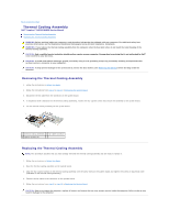
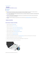
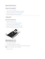
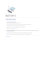
1 display assembly 3 Mini-Card antenna cables 2 screws (2) 4 display cable connector Replacing the Display Assembly 1. Follow the instructions in Before You Begin. 2. Place the display assembly in position and replace the two screws (one on each side) that secure the display assembly to the computer base. 3. Connect the display cable to the connector on the system board. 4. Route the antenna cables through the routing guides and connect the cables to the Mini-Card (see Replacing the Mini-Card). 5. Replace the palm rest (see Replacing the Palm Rest). 6. Replace the keyboard (see Replacing the Keyboard). 7. Replace the memory module(s) (see Replacing the Memory Module(s)). 8. Replace the module cover (see Replacing the Module Cover). 9. Follow the instructions from step 3 to step 4 in Replacing the Optical Drive. 10. Follow the instructions from step 4 to step 5 in Replacing the Hard Drive. 11. Replace the battery (see Replacing the Battery). CAUTION: Before turning on the computer, replace all screws and ensure that no stray screws remain inside the computer. Failure to do so may result in damage to the computer. Display Bezel Removing the Display Bezel CAUTION: The display bezel is extremely fragile. Be careful when removing it to prevent damaging the bezel. 1. Follow the instructions in Before You Begin. 2. Remove the display assembly (see Removing the Display Assembly). 3. Make a note of the Mini-Card antenna cables and the display cable routing on the display hinges. 4. Using your fingertips, carefully pry up the inside edge of the display bezel. 5. Remove the display bezel.
-
 1
1 -
2
-
3
-
4
-
5
-
6
-
7
-
8
-
9
-
10
-
11
-
12
-
 13
13 -
 14
14 -
 15
15 -
 16
16 -
 17
17 -
 18
18 -
 19
19 -
 20
20 -
 21
21 -
 22
22 -
 23
23 -
24
-
25
-
26
-
27
-
28
-
29
-
30
-
31
-
32
-
33
-
34
-
35
-
36
-
37
-
38
-
39
-
40
-
41
-
42
-
43
-
44
-
45
-
46
-
47
 |
 |