Dell Inspiron 17 5755 Service Manual - Page 58
Replacing the heat-sink assembly, Procedure, Post-requisites
 |
View all Dell Inspiron 17 5755 manuals
Add to My Manuals
Save this manual to your list of manuals |
Page 58 highlights
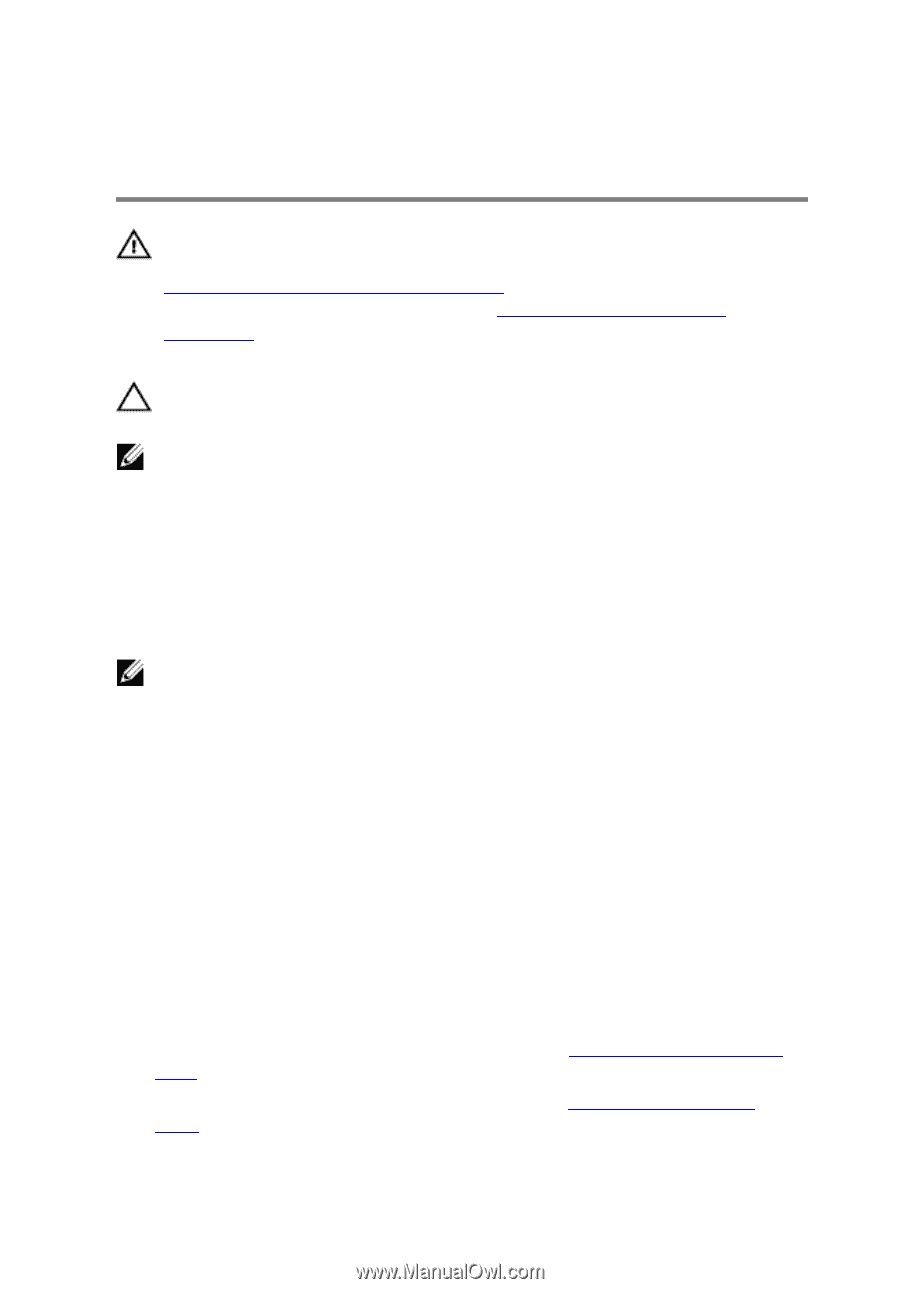
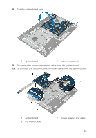
Replacing the heat-sink assembly WARNING: Before working inside your computer, read the safety information that shipped with your computer and follow the steps in Before working inside your computer. After working inside your computer, follow the instructions in After working inside your computer. For more safety best practices, see the Regulatory Compliance home page at dell.com/regulatory_compliance. CAUTION: Incorrect alignment of the heat sink can cause damage to the system board and processor. NOTE: The original thermal grease can be reused if the original system board and fan are reinstalled together. If either the system board or the fan is replaced, use the thermal pad provided in the kit to ensure that thermal conductivity is achieved. Procedure NOTE: The original thermal grease can be reused, if the original system board and fan are reinstalled together. If either the system board or the fan is replaced, use the thermal pad provided in the kit to make sure that thermal conductivity is achieved. 1 Align the screw holes on the heat-sink assembly with the screw holes on the system board. 2 In sequential order, as indicated on the heat-sink assembly, tighten the captive screws that secure the heat-sink assembly to the system board. 3 Replace the screws that secure the heat-sink assembly to the system board. 4 Connect the fan cable to the system board. Post-requisites 1 Follow the procedure from step 3 to step 8 in "Replacing the computer base". 2 Follow the procedure from step 4 to step 7 in "Replacing the optical drive". 58
-
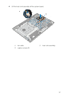
 1
1 -
2
-
3
-
4
-
5
-
6
-
7
-
8
-
9
-
10
-
11
-
12
-
13
-
14
-
15
-
16
-
17
-
18
-
19
-
20
-
21
-
22
-
23
-
24
-
25
-
26
-
27
-
28
-
29
-
30
-
31
-
32
-
33
-
34
-
35
-
36
-
37
-
38
-
39
-
40
-
41
-
42
-
43
-
44
-
45
-
46
-
47
-
48
-
49
-
50
-
51
-
52
-
 53
53 -
 54
54 -
 55
55 -
 56
56 -
 57
57 -
 58
58 -
 59
59 -
 60
60 -
 61
61 -
 62
62 -
 63
63 -
64
-
65
-
66
-
67
-
68
-
69
-
70
-
71
-
72
-
73
-
74
-
75
-
76
-
77
-
78
-
79
-
80
-
81
-
82
-
83
-
84
-
85
-
86
-
87
-
88
-
89
-
90
-
91
-
92
-
93
-
94
-
95
-
96
-
97
-
98
-
99
-
100
-
101
-
102
-
103
-
104
-
105
-
106
-
107
-
108
 |
 |