Dell Inspiron 17 N7010 Inspiron 17 N7010 Service Manual - Page 61
Replacing the System Board
 |
View all Dell Inspiron 17 N7010 manuals
Add to My Manuals
Save this manual to your list of manuals |
Page 61 highlights
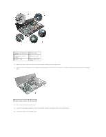
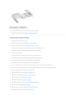
1 captive screws (2) 2 PCH cooler 21. Remove the processor heat sink (see Removing the Processor Heat Sink). 22. Remove the processor module (see Removing the Processor Module). Replacing the System Board 1. Follow the instructions in Before You Begin. 2. Replace the processor module (see Replacing the Processor Module). 3. Replace the processor heat sink (see Replacing the Processor Heat Sink). 4. Align the captive screws on the PCH cooler with the screw holes on the system board. 5. Tighten the two captive screws that secure the PCH cooler to the system board. 6. Turn the system board over. 7. Align the connectors on the system board with the slots on the computer base. 8. Use the alignment posts on the computer base to correctly place the system board. 9. Replace the eight screws that secure the system board to the computer base. 10. Connect the status light board cable to the connector on the system board. 11. Connect the display cable to the connector on the system board, and replace the display cable grounding screw. 12. Connect the speaker cable, subwoofer cable, and the AC adapter connector cable to the connectors on the system board. 13. Replace the processor fan (see Replacing the Processor Fan). 14. Replace the Bluetooth card (see Replacing the Bluetooth Card). 15. Replace the coin-cell battery (see Replacing the Coin-Cell Battery). 16. Replace the palm rest (see Replacing the Palm Rest). 17. Replace the keyboard (see Replacing the Keyboard). 18. Follow the instructions from step 5 to step 7 in Replacing the Hard Drive. 19. Replace the Mini-Card (see Replacing the Mini-Card). 20. Replace the memory module(s) (see Replacing the Memory Module(s)). 21. Replace the module cover (see Replacing the Module Cover).
-
 1
1 -
2
-
3
-
4
-
5
-
6
-
7
-
8
-
9
-
10
-
11
-
12
-
13
-
14
-
15
-
16
-
17
-
18
-
19
-
20
-
21
-
22
-
23
-
24
-
25
-
26
-
27
-
28
-
29
-
30
-
31
-
32
-
33
-
34
-
35
-
36
-
37
-
38
-
39
-
40
-
41
-
42
-
43
-
44
-
45
-
46
-
47
-
48
-
49
-
50
-
51
-
52
-
53
-
54
-
55
-
 56
56 -
 57
57 -
 58
58 -
 59
59 -
 60
60 -
 61
61 -
 62
62 -
 63
63
 |
 |
