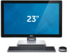
Dell Inspiron 23 2350 Service Manual - Page 82
Replacing the Stand Assembly, Procedure, Post-requisites, For more safety best practices
 |
View all Dell Inspiron 23 2350 manuals
Add to My Manuals
Save this manual to your list of manuals |
Page 82 highlights
Replacing the Stand Assembly WARNING: Before working inside your computer, read the safety information that shipped with your computer and follow the steps in Before Working Inside Your Computer. After working inside your computer, follow the instructions in After Working Inside Your Computer. For more safety best practices, see the Regulatory Compliance home page at dell.com/regulatory_compliance. Procedure 1 Place the stand assembly on the display assembly. 2 Connect the touchscreen cable to the display panel and adhere the Mylar over the touchscreen cable. 3 Slide the tabs on the stand assembly into the slots on the display bracket. 4 Align the screw holes on the stand assembly with the screw holes on the display bracket. 5 Replace the screws that secure the stand assembly to the display bracket. 6 Route all the cables through their routing guides. For more information, see display panel with stand assembly. 7 Replace the screws that secure the cables to the display bracket. 8 Connect the power-button cable to the control-buttons board cable. 9 Connect the control-buttons board cable to the control-buttons board. 10 Slide the display cable into the display-cable connector slot and connect the display cable to the display assembly. 11 Align the antenna modules with the alignment posts and adhere them to the display bezel. 12 Connect the converter-board cable and the display-backlight cable to the converter board. Post-requisites 1 Replace the microphones. 2 Replace the camera. 3 Replace the back cover. 4 Replace the computer base. 82
-
 1
1 -
2
-
3
-
4
-
5
-
6
-
7
-
8
-
9
-
10
-
11
-
12
-
13
-
14
-
15
-
16
-
17
-
18
-
19
-
20
-
21
-
22
-
23
-
24
-
25
-
26
-
27
-
28
-
29
-
30
-
31
-
32
-
33
-
34
-
35
-
36
-
37
-
38
-
39
-
40
-
41
-
42
-
43
-
44
-
45
-
46
-
47
-
48
-
49
-
50
-
51
-
52
-
53
-
54
-
55
-
56
-
57
-
58
-
59
-
60
-
61
-
62
-
63
-
64
-
65
-
66
-
67
-
68
-
69
-
70
-
71
-
72
-
73
-
74
-
75
-
76
-
 77
77 -
 78
78 -
 79
79 -
 80
80 -
 81
81 -
 82
82 -
 83
83 -
 84
84 -
 85
85 -
 86
86 -
 87
87 -
88
-
89
-
90
-
91
-
92
-
93
-
94
-
95
-
96
-
97
-
98
-
99
-
100
-
101
-
102
-
103
-
104
-
105
-
106
 |
 |
