Dell Inspiron 24 3459 Service Manual
Dell Inspiron 24 3459 Manual
 |
View all Dell Inspiron 24 3459 manuals
Add to My Manuals
Save this manual to your list of manuals |
Dell Inspiron 24 3459 manual content summary:
- Dell Inspiron 24 3459 | Service Manual - Page 1
Inspiron 24 3000 Series Service Manual Computer Model: Inspiron 24-3459 Regulatory Model: W12C Regulatory Type: W12C003 - Dell Inspiron 24 3459 | Service Manual - Page 2
potential damage to hardware or loss of data and tells you how to avoid the problem. WARNING: A WARNING indicates a potential for property damage, personal injury, or death. Copyright © 2015 Dell Inc. All rights reserved. This product is protected by U.S. and international copyright and intellectual - Dell Inspiron 24 3459 | Service Manual - Page 3
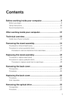
Before you begin 9 Safety instructions 10 Recommended tools 11 replace pedestal stand 19 Procedure to replace stand riser to stand base 19 Removing the back cover 20 Prerequisites...20 Procedure...20 Replacing the back cover 22 Procedure...22 Post-requisites 22 Removing the optical drive - Dell Inspiron 24 3459 | Service Manual - Page 4
26 Procedure...26 Post-requisites 26 Removing the hard drive 27 Prerequisites...27 Procedure...27 Replacing the hard drive 30 Procedure...30 Post-requisites 30 Removing the memory module 31 Prerequisites...31 Procedure...31 Replacing the memory module 33 Procedure...33 Post-requisites 34 - Dell Inspiron 24 3459 | Service Manual - Page 5
Procedure...41 Post-requisites 41 Removing the fan 42 Prerequisites...42 Procedure...42 Replacing the fan 44 Procedure...44 Post-requisites 44 Removing the coin-cell battery 45 Prerequisites...45 Procedure...46 Replacing the coin-cell battery 47 Procedure...47 Post-requisites 47 Removing the - Dell Inspiron 24 3459 | Service Manual - Page 6
Post-requisites 53 Removing the system board 54 Prerequisites...54 Procedure...54 Replacing the system board 57 Procedure...57 Post-requisites 57 Removing the VESA-mount bracket 58 Prerequisites...58 Procedure...58 Replacing the VESA-mount bracket 60 Procedure...60 Post-requisites 60 Removing - Dell Inspiron 24 3459 | Service Manual - Page 7
-requisites 69 Removing the display assembly 70 Prerequisites...70 Procedure...71 Replacing the display assembly 75 Procedure...75 Post-requisites 75 Removing the rubber feet 77 Prerequisites...77 Procedure...77 Replacing the rubber feet 79 Procedure...79 Post-requisites 79 Clearing Forgotten - Dell Inspiron 24 3459 | Service Manual - Page 8
Clearing CMOS Settings 82 Prerequisites...82 Procedure...82 Post-requisites 83 Flashing the BIOS 84 Getting help and contacting Dell 85 Self-help resources 85 Contacting Dell 86 8 - Dell Inspiron 24 3459 | Service Manual - Page 9
down. - Windows 8.1: On the Start screen, click or tap the power icon → Shut down. - Windows 7: Click or tap Start → Shut down. NOTE: If you are using a different operating system, see the documentation of your operating system for shut-down instructions. 3 Disconnect your computer and all attached - Dell Inspiron 24 3459 | Service Manual - Page 10
computer, replace all covers, panels, and screws before connecting to the power source. troubleshooting and repairs as authorized or directed by the Dell technical assistance team. Damage due to servicing that is not authorized by Dell is not covered by your warranty. See the safety instructions - Dell Inspiron 24 3459 | Service Manual - Page 11
Recommended tools The procedures in this document may require the following tools: • Phillips screwdriver • Plastic scribe 11 - Dell Inspiron 24 3459 | Service Manual - Page 12
that no stray screws remain inside your computer. 2 Connect any external devices, peripherals, and cables you removed before working on your computer. 3 Replace any media cards, discs, and any other parts that you removed before working on your computer. 4 Connect your computer and all attached - Dell Inspiron 24 3459 | Service Manual - Page 13
the Regulatory Compliance home page at www.dell.com/regulatory_compliance. Inside view of your computer 1 control-buttons board 3 optical-drive assembly 5 microphone board 7 fan 9 wireless card 11 coin-cell battery 13 VESA-mount bracket 2 hard-drive assembly 4 display-assembly base 6 camera module - Dell Inspiron 24 3459 | Service Manual - Page 14
working inside your computer. After working inside your computer, follow the instructions in After working inside your computer. For more safety best practices, see the Regulatory Compliance home page at www.dell.com/regulatory_compliance. Procedure to remove easel stand NOTE: The type of stand - Dell Inspiron 24 3459 | Service Manual - Page 15
5 Lift the stand off the back cover. 1 stand 3 screws (2) 2 stand bracket 4 back cover Procedure to remove pedestal stand NOTE: The type of stand assembly varies depending on the configuration you ordered. 1 Place the computer face down on a soft cloth or a clean surface. 2 Release the tabs on - Dell Inspiron 24 3459 | Service Manual - Page 16
3 Slide and remove the stand cover away from the computer. 1 stand cover 2 back cover 4 Remove the screws that secure the stand to the display-panel base. 5 Lift the stand upward at an angle and slide it away from the computer. 1 back cover 3 stand 16 2 screws (4) - Dell Inspiron 24 3459 | Service Manual - Page 17
Procedure to remove stand riser from stand base NOTE: If you need to remove either the stand base or stand riser from the stand assembly, follow the steps below. 1 Lift the screw handle on the stand base. 2 Using the screw handle, loosen the captive thumbscrew that secures the stand base to the - Dell Inspiron 24 3459 | Service Manual - Page 18
3 Slide the stand base off the stand riser. 1 stand riser 2 stand base 18 - Dell Inspiron 24 3459 | Service Manual - Page 19
your computer. After working inside your computer, follow the instructions in After working inside your computer. For more safety best practices, see the Regulatory Compliance home page at www.dell.com/regulatory_compliance. Procedure to replace easel stand NOTE: The type of stand assembly varies - Dell Inspiron 24 3459 | Service Manual - Page 20
inside your computer. After working inside your computer, follow the instructions in After working inside your computer. For more safety best practices, see the Regulatory Compliance home page at www.dell.com/regulatory_compliance. Prerequisites Remove the stand assembly. Procedure CAUTION: Do - Dell Inspiron 24 3459 | Service Manual - Page 21
2 Lift the back cover off the computer. 1 display bezel 3 plastic scribe 2 back cover 21 - Dell Inspiron 24 3459 | Service Manual - Page 22
Before working inside your computer. After working inside your computer, follow the instructions in After working inside your computer. For more safety best practices, see the Regulatory Compliance home page at www.dell.com/regulatory_compliance. Procedure Align the tabs on the back cover with the - Dell Inspiron 24 3459 | Service Manual - Page 23
Regulatory Compliance home page at www.dell.com/regulatory_compliance. Prerequisites 1 Remove the stand assembly. 2 Remove the back cover. Procedure 1 Disconnect the power and data cable from the optical drive. 2 Remove the screw that secures the optical-drive assembly to the display- assembly base - Dell Inspiron 24 3459 | Service Manual - Page 24
3 Slide the optical-drive assembly out of the optical-drive bay. 1 optical-drive assembly 3 power and data cable 2 screw 4 Carefully pull the optical-drive bezel and remove it from the optical drive. 5 Remove the screw that secures the optical-drive bracket to the optical drive. 24 - Dell Inspiron 24 3459 | Service Manual - Page 25
6 Remove the optical-drive bracket from the optical drive. 1 screw 3 optical drive 2 optical-drive bracket 4 optical-drive bezel 25 - Dell Inspiron 24 3459 | Service Manual - Page 26
, follow the instructions in After working inside your computer. For more safety best practices, see the Regulatory Compliance home page at www.dell.com/regulatory_compliance. Procedure 1 Align the screw hole on the optical-drive bracket with the screw hole on the optical drive. 2 Replace the screw - Dell Inspiron 24 3459 | Service Manual - Page 27
instructions in After working inside your computer. For more safety best practices, see the Regulatory Compliance home page at www.dell.com/regulatory_compliance. CAUTION: Hard drives are fragile. Exercise care when handling the hard drive. CAUTION: To avoid data loss, do not remove the hard drive - Dell Inspiron 24 3459 | Service Manual - Page 28
3 Using your fingertips, slide the hard-drive assembly out of the hard-drive bay. 1 power and data cable 3 screw 2 hard-drive assembly 4 display-assembly base 4 Remove the screws that secure the hard-drive bracket to the hard drive. 28 - Dell Inspiron 24 3459 | Service Manual - Page 29
5 Remove the hard drive from the hard-drive bracket. 1 screws (3) 3 hard-drive bracket 2 hard drive 29 - Dell Inspiron 24 3459 | Service Manual - Page 30
at www.dell.com/regulatory_compliance. CAUTION: Hard drives are fragile. Exercise care when handling the hard drive. Procedure 1 Align the screw holes on the hard-drive bracket with the screw holes on the hard drive. 2 Replace the screws that secure the hard-drive bracket to the hard drive. 3 Slide - Dell Inspiron 24 3459 | Service Manual - Page 31
working inside your computer. After working inside your computer, follow the instructions in After working inside your computer. For more safety best practices, see the Regulatory Compliance home page at www.dell.com/regulatory_compliance. Prerequisites 1 Remove the stand assembly. 2 Remove the back - Dell Inspiron 24 3459 | Service Manual - Page 32
2 Remove the memory module from the memory-module slot. 1 system board 3 memory module 2 securing clips (2) 4 memory-module slot 32 - Dell Inspiron 24 3459 | Service Manual - Page 33
Before working inside your computer. After working inside your computer, follow the instructions in After working inside your computer. For more safety best practices, see the Regulatory Compliance home page at www.dell.com/regulatory_compliance. Procedure 1 Align the notch on the memory module with - Dell Inspiron 24 3459 | Service Manual - Page 34
into place. NOTE: If you do not hear the click, remove the memory module and reinstall it. 1 notch 3 securing clips (2) 5 memory-module slot Post-requisites 1 Replace the back cover. 2 Replace the stand assembly. 2 tab 4 memory module 34 - Dell Inspiron 24 3459 | Service Manual - Page 35
working inside your computer. After working inside your computer, follow the instructions in After working inside your computer. For more safety best practices, see the Regulatory Compliance home page at www.dell.com/regulatory_compliance. Prerequisites 1 Remove the stand assembly. 2 Remove the back - Dell Inspiron 24 3459 | Service Manual - Page 36
4 Slide the wireless card out of the wireless-card slot. 1 wireless-card bracket 3 screw 5 wireless card 2 antenna cables 4 wireless-card slot 6 system board 36 - Dell Inspiron 24 3459 | Service Manual - Page 37
instructions in After working inside your computer. For more safety best practices, see the Regulatory Compliance home page at www.dell. following table provides the antenna-cable color scheme for the wireless card supported by your computer: Connectors on the wireless card Main (white triangle) - Dell Inspiron 24 3459 | Service Manual - Page 38
6 Replace the screw that secures the wireless-card bracket and the wireless card to the system board. 1 antenna cables 3 screw 5 wireless-card slot 7 notch Post-requisites 1 Replace the back cover. 2 Replace the stand assembly. 2 wireless-card bracket 4 wireless card 6 tab 38 - Dell Inspiron 24 3459 | Service Manual - Page 39
Before working inside your computer. After working inside your computer, follow the instructions in After working inside your computer. For more safety best practices, see the Regulatory Compliance home page at www.dell.com/regulatory_compliance. WARNING: The heat sink may become hot during normal - Dell Inspiron 24 3459 | Service Manual - Page 40
3 Lift the heat sink off the system board. 1 system board 3 heat sink 5 display-assembly base 2 captive screws (5) 4 screw 40 - Dell Inspiron 24 3459 | Service Manual - Page 41
follow the instructions in After working inside your computer. For more safety best practices, see the Regulatory Compliance home page at www.dell.com/regulatory_compliance the heat sink to the system board. 4 Replace the screw that secures the heat sink to the display-assembly base. Post-requisites - Dell Inspiron 24 3459 | Service Manual - Page 42
working inside your computer. After working inside your computer, follow the instructions in After working inside your computer. For more safety best practices, see the Regulatory Compliance home page at www.dell.com/regulatory_compliance. Prerequisites 1 Remove the stand assembly. 2 Remove the back - Dell Inspiron 24 3459 | Service Manual - Page 43
3 Lift the fan at an angle off the display-assembly base. 1 fan cable 3 fan 5 display-assembly base 2 system board 4 screws (2) 43 - Dell Inspiron 24 3459 | Service Manual - Page 44
inside your computer. After working inside your computer, follow the instructions in After working inside your computer. For more safety best practices, see the Regulatory Compliance home page at www.dell.com/regulatory_compliance. Procedure 1 Replace the fan at an angle on the display-assembly base - Dell Inspiron 24 3459 | Service Manual - Page 45
working inside your computer, follow the instructions in After working inside your computer. For more safety best practices, see the Regulatory Compliance home page at www.dell.com/regulatory_compliance. CAUTION: Removing the coin-cell battery resets the BIOS setup program's settings to default - Dell Inspiron 24 3459 | Service Manual - Page 46
Procedure Using a plastic scribe, gently pry out the coin-cell battery out of the battery socket on the system board. 1 system board 3 coin-cell battery 2 plastic scribe 4 battery socket 46 - Dell Inspiron 24 3459 | Service Manual - Page 47
working inside your computer. After working inside your computer, follow the instructions in After working inside your computer. For more safety best practices, see the Regulatory Compliance home page at www.dell.com/regulatory_compliance. Procedure With the positive-side facing up, insert the - Dell Inspiron 24 3459 | Service Manual - Page 48
working inside your computer. After working inside your computer, follow the instructions in After working inside your computer. For more safety best practices, see the Regulatory Compliance home page at www.dell.com/regulatory_compliance. Prerequisites 1 Remove the stand assembly. 2 Remove the back - Dell Inspiron 24 3459 | Service Manual - Page 49
5 Disconnect the microphone and camera cable from the microphone board. 1 microphone and camera cable 3 display bezel 5 microphone board 2 routing guides 4 display-assembly base 49 - Dell Inspiron 24 3459 | Service Manual - Page 50
instructions in After working inside your computer. For more safety best practices, see the Regulatory Compliance home page at www.dell.com from step 1 to step 3 in "Replacing the camera". 4 Route the microphone and camera cable through the routing guides on the display-assembly base. 5 Connect the - Dell Inspiron 24 3459 | Service Manual - Page 51
working inside your computer. After working inside your computer, follow the instructions in After working inside your computer. For more safety best practices, see the Regulatory Compliance home page at www.dell.com/regulatory_compliance. Prerequisites 1 Remove the stand assembly. 2 Remove the back - Dell Inspiron 24 3459 | Service Manual - Page 52
7 Disconnect the microphone and camera cable from the camera module. 1 securing clip 3 camera module 2 tab 4 microphone and camera cable 52 - Dell Inspiron 24 3459 | Service Manual - Page 53
instructions in After working inside your computer. For more safety best practices, see the Regulatory Compliance home page at www.dell. from step 1 to step 2 in "Replacing the microphone". 5 Route the microphone and camera cable through the routing guides on the display-assembly base. 6 Connect - Dell Inspiron 24 3459 | Service Manual - Page 54
after you replace the system board. Prerequisites 1 Remove the stand assembly. 2 Remove the back cover. 3 Remove the heat sink. 4 Remove the wireless card. Procedure 1 Disconnect the speaker, touch-control board, hard-drive cable, opticaldrive cable, hard-drive and optical-drive power, fan, and - Dell Inspiron 24 3459 | Service Manual - Page 55
cable from its connector on the system board. 1 speaker cable 3 control-buttons board cable 5 display cable 7 hard-drive data cable 9 hard-drive and optical-drive power cable 11 microphone and camera cable 2 touch-control board cable 4 display-backlight cable 6 display-assembly base 8 optical - Dell Inspiron 24 3459 | Service Manual - Page 56
5 Carefully lift the system board from the inner edge and release the ports from the slots on the display-assembly base. 6 Lift the system board off the display-assembly base. 1 system board 3 screws (4) 2 slots 4 display-assembly base 56 - Dell Inspiron 24 3459 | Service Manual - Page 57
-control board, hard-drive data cable, and optical-drive data, hard-drive and optical-drive power, fan, and microphone and camera cables to its connectors on the system board. Post-requisites 1 Replace the wireless card. 2 Replace the heat sink. 3 Replace the back cover. 4 Replace the stand assembly - Dell Inspiron 24 3459 | Service Manual - Page 58
working inside your computer. After working inside your computer, follow the instructions in After working inside your computer. For more safety best practices, see the Regulatory Compliance home page at www.dell.com/regulatory_compliance. Prerequisites 1 Remove the stand assembly. 2 Remove the back - Dell Inspiron 24 3459 | Service Manual - Page 59
3 Lift the VESA-mount bracket off the display-assembly base. 1 display-assembly base 3 VESA-mount bracket 5 routing guides 2 screws (4) 4 speaker cable 59 - Dell Inspiron 24 3459 | Service Manual - Page 60
the instructions in After working inside your computer. For more safety best practices, see the Regulatory Compliance home page at www.dell.com/regulatory_compliance. Procedure 1 Align the screw holes on the VESA-mount bracket with the screw holes on the display-assembly base. 2 Replace the screws - Dell Inspiron 24 3459 | Service Manual - Page 61
working inside your computer. After working inside your computer, follow the instructions in After working inside your computer. For more safety best practices, see the Regulatory Compliance home page at www.dell.com/regulatory_compliance. Prerequisites 1 Remove the stand assembly. 2 Remove the back - Dell Inspiron 24 3459 | Service Manual - Page 62
3 Lift the speaker cover off the display bezel. 1 screws (4) 3 display-assembly base 2 speaker cover 62 - Dell Inspiron 24 3459 | Service Manual - Page 63
working inside your computer. After working inside your computer, follow the instructions in After working inside your computer. For more safety best practices, see the Regulatory Compliance home page at www.dell.com/regulatory_compliance. Procedure 1 Align the screw holes on the speaker cover - Dell Inspiron 24 3459 | Service Manual - Page 64
working inside your computer. After working inside your computer, follow the instructions in After working inside your computer. For more safety best practices, see the Regulatory Compliance home page at www.dell.com/regulatory_compliance. Prerequisites 1 Remove the stand assembly. 2 Remove the back - Dell Inspiron 24 3459 | Service Manual - Page 65
7 Lift the speakers, along with the speaker cable, off the display bezel. 1 screw 3 speaker-cable routing 5 speaker cable 7 speakers (2) 2 tape 4 VESA-mount bracket 6 rubber grommets (4) 65 - Dell Inspiron 24 3459 | Service Manual - Page 66
instructions in After working inside your computer. For more safety best practices, see the Regulatory Compliance home page at www.dell guide on the display bezel. 3 Adhere the tape that secures the speaker cable to the VESA-mount bracket. 4 Replace the screw to the VESA-mount bracket. 5 Replace - Dell Inspiron 24 3459 | Service Manual - Page 67
instructions in After working inside your computer. For more safety best practices, see the Regulatory Compliance home page at www.dell. the control-buttons board cable routing and peel it off from its routing guides on the display-assembly base. 3 Using your fingertips, press the securing clips - Dell Inspiron 24 3459 | Service Manual - Page 68
5 Lift the latch and disconnect the control-buttons board cable from the control-buttons board. 1 latch 3 control-buttons board cable 5 control-buttons board 2 system board 4 latch 6 securing clips (2) 68 - Dell Inspiron 24 3459 | Service Manual - Page 69
instructions in After working inside your computer. For more safety best practices, see the Regulatory Compliance home page at www.dell. the cable. 2 Replace the control-buttons board into the slot on the display bezel. 3 Route the control-buttons board cable through the routing guides and adhere the - Dell Inspiron 24 3459 | Service Manual - Page 70
the instructions in After working inside your computer. For more safety best practices, see the Regulatory Compliance home page at www.dell.com/regulatory_compliance. Prerequisites 1 Remove the stand assembly. 2 Remove the back cover. 3 Remove the optical drive. 4 Remove the hard drive. 5 Remove - Dell Inspiron 24 3459 | Service Manual - Page 71
Procedure 1 Note the optical drive and hard drive cables' routing and remove the cables from its routing guides on the display-assembly base. 1 routing guides 3 optical-drive cable 2 hard-drive cable 4 display-assembly base 71 - Dell Inspiron 24 3459 | Service Manual - Page 72
2 Remove the screws that secure the display-assembly base to the display bezel. 1 screws (19) 2 display-assembly base 3 Release the display-panel base from the tabs on the display bezel. 4 Slide the display cable through the slot on the display-assembly base. 72 - Dell Inspiron 24 3459 | Service Manual - Page 73
5 Lift the display-assembly base off the display panel. 1 tabs (6) 3 display cable 2 display-assembly base 4 slot 73 - Dell Inspiron 24 3459 | Service Manual - Page 74
1 display assembly 74 - Dell Inspiron 24 3459 | Service Manual - Page 75
the optical drive and hard drive cables through the routing guides on the display-assembly base. Post-requisites 1 Replace the control-buttons board. 2 Replace the speakers. 3 Replace the speaker cover. 4 Replace the VESA-mount bracket. 5 Replace the system board. 6 Replace the camera. 7 Replace the - Dell Inspiron 24 3459 | Service Manual - Page 76
15 Replace the back cover. 16 Replace the stand assembly. 76 - Dell Inspiron 24 3459 | Service Manual - Page 77
the instructions in After working inside your computer. For more safety best practices, see the Regulatory Compliance home page at www.dell.com/regulatory_compliance. Prerequisites 1 Remove the stand assembly. 2 Remove the back cover. 3 Remove the optical drive. 4 Remove the hard drive. 5 Remove - Dell Inspiron 24 3459 | Service Manual - Page 78
2 Lift the rubber feet off the display bezel. 1 rubber feet (2) 3 display bezel 2 screws (2) 78 - Dell Inspiron 24 3459 | Service Manual - Page 79
bracket. 6 Replace the system board. 7 Replace the camera. 8 Replace the microphone. 9 Replace the coin-cell battery. 10 Replace the fan. 11 Replace the heat sink. 12 Replace the wireless card. 13 Replace the memory module. 14 Replace the hard drive. 15 Replace the optical drive. 16 Replace the back - Dell Inspiron 24 3459 | Service Manual - Page 80
working inside your computer. After working inside your computer, follow the instructions in After working inside your computer. For more safety best practices, see the Regulatory Compliance home page at www.dell.com/regulatory_compliance. Prerequisites 1 Remove the stand assembly. 2 Remove the back - Dell Inspiron 24 3459 | Service Manual - Page 81
2 Wait for 5 seconds and then replace the jumper plug in its original location. 1 jumper plug Post-requisites 1 Replace the back cover. 2 Replace the stand assembly. 2 password jumper-pins 81 - Dell Inspiron 24 3459 | Service Manual - Page 82
working inside your computer. After working inside your computer, follow the instructions in After working inside your computer. For more safety best practices, see the Regulatory Compliance home page at www.dell.com/regulatory_compliance. Prerequisites 1 Remove the stand assembly. 2 Remove the back - Dell Inspiron 24 3459 | Service Manual - Page 83
2 Wait for 5 seconds and then replace the jumper plug to its original location. 1 jumper plug 3 CMOS jumper-pins Post-requisites 1 Replace the back cover. 2 Replace the stand assembly. 2 Password jumper-pins 83 - Dell Inspiron 24 3459 | Service Manual - Page 84
dell.com/support. 3 Click Product Support, enter the Service Tag of your computer and click Submit. NOTE: If you do not have the Service Tag, use the auto-detect feature or manually browse for your computer model. 4 Click Drivers the BIOS update file icon and follow the instructions on the screen. 84 - Dell Inspiron 24 3459 | Service Manual - Page 85
. Online help for operating system www.dell.com/support/windows www.dell.com/support/linux Troubleshooting information, user manuals, setup instructions, product specifications, technical help blogs, drivers, software updates, and so on www.dell.com/support Learn about your operating system - Dell Inspiron 24 3459 | Service Manual - Page 86
Contacting Dell To contact Dell for sales, technical support, or customer service issues, see www.dell.com/contactdell. NOTE: Availability varies by country and product, and some services may not be available in your country. NOTE: If you do not have an active internet connection, you can find
-
 1
1 -
 2
2 -
 3
3 -
 4
4 -
 5
5 -
 6
6 -
 7
7 -
8
-
9
-
10
-
11
-
12
-
13
-
14
-
15
-
16
-
17
-
18
-
19
-
20
-
21
-
22
-
23
-
24
-
25
-
26
-
27
-
28
-
29
-
30
-
31
-
32
-
33
-
34
-
35
-
36
-
37
-
38
-
39
-
40
-
41
-
42
-
43
-
44
-
45
-
46
-
47
-
48
-
49
-
50
-
51
-
52
-
53
-
54
-
55
-
56
-
57
-
58
-
59
-
60
-
61
-
62
-
63
-
64
-
65
-
66
-
67
-
68
-
69
-
70
-
71
-
72
-
73
-
74
-
75
-
76
-
77
-
78
-
79
-
80
-
81
-
82
-
83
-
84
-
85
-
86
 |
 |

Inspiron 24
3000 Series
Service Manual
Computer Model: Inspiron 24–3459
Regulatory Model: W12C
Regulatory Type: W12C003