Dell Inspiron 24 5475 Inspiron 24 5000 Service Manual - Page 110
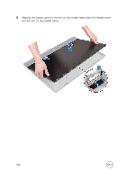
Replace the seven remaining screws M3x5 that secure the middle frame to
 |
View all Dell Inspiron 24 5475 manuals
Add to My Manuals
Save this manual to your list of manuals |
Page 110 highlights
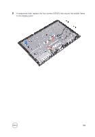
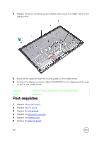
4 Replace the seven remaining screws (M3x5) that secure the middle frame to the display panel. 5 Route all the cables through the routing guides on the middle frame. 6 Connect the display converter cable (CONVERTER) to the display panel through its slot on the middle frame. Identifier GUID-37F0AD22-4B4B-4FED-912B-2B9782400AA6 Status Released Post-requisites 1 Replace the system board. 2 Replace the I/O board. 3 Replace the I/O bracket. 4 Replace the processor heat-sink. 5 Replace the wireless card. 6 Replace the side I/O-board. 110
-
 1
1 -
2
-
3
-
4
-
5
-
6
-
7
-
8
-
9
-
10
-
11
-
12
-
13
-
14
-
15
-
16
-
17
-
18
-
19
-
20
-
21
-
22
-
23
-
24
-
25
-
26
-
27
-
28
-
29
-
30
-
31
-
32
-
33
-
34
-
35
-
36
-
37
-
38
-
39
-
40
-
41
-
42
-
43
-
44
-
45
-
46
-
47
-
48
-
49
-
50
-
51
-
52
-
53
-
54
-
55
-
56
-
57
-
58
-
59
-
60
-
61
-
62
-
63
-
64
-
65
-
66
-
67
-
68
-
69
-
70
-
71
-
72
-
73
-
74
-
75
-
76
-
77
-
78
-
79
-
80
-
81
-
82
-
83
-
84
-
85
-
86
-
87
-
88
-
89
-
90
-
91
-
92
-
93
-
94
-
95
-
96
-
97
-
98
-
99
-
100
-
101
-
102
-
103
-
104
-
 105
105 -
 106
106 -
 107
107 -
 108
108 -
 109
109 -
 110
110 -
 111
111 -
 112
112 -
 113
113 -
 114
114 -
 115
115 -
116
-
117
-
118
-
119
-
120
-
121
-
122
-
123
-
124
-
125
-
126
-
127
-
128
-
129
-
130
-
131
-
132
-
133
-
134
 |
 |

4
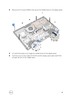
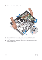
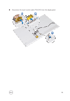
Replace the seven remaining screws (M3x5) that secure the middle frame to the
display panel.
5
Route all the cables through the routing guides on the middle frame.
6
Connect the display converter cable (CONVERTER) to the display panel through
its slot on the middle frame.
Identifier
GUID-37F0AD22-4B4B-4FED-912B-2B9782400AA6
Status
Released
Post-requisites
1
Replace the
system board
.
2
Replace the
I/O board
.
3
Replace the
I/O bracket
.
4
Replace the
processor heat-sink
.
5
Replace the
wireless card
.
6
Replace the
side I/O-board
.
110