Dell Inspiron 3670 Service Manual - Page 33
Replacing the optical drive, Procedure
 |
View all Dell Inspiron 3670 manuals
Add to My Manuals
Save this manual to your list of manuals |
Page 33 highlights
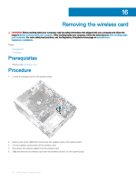
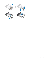
19 Replacing the optical drive WARNING: Before working inside your computer, read the safety information that shipped with your computer and follow the steps in Before working inside your computer. After working inside your computer, follow the instructions in After working inside your computer. For more safety best practices, see the Regulatory Compliance home page at www.dell.com/ regulatory_compliance. Topics: • Procedure • Post-requisites Procedure 1 Align and replace the optical-drive bezel to the optical-drive tray. 2 Slide the optical-drive assembly into its slot on the chassis and align the screw holes on the optical-drive assembly to the screw holes on the chassis. 3 Replace the screws (M2x2) that secures the optical-drive assembly to the chassis. 4 Connect the optical-drive data cable and power cable to the optical-drive assembly. Replacing the optical drive 33
-
 1
1 -
2
-
3
-
4
-
5
-
6
-
7
-
8
-
9
-
10
-
11
-
12
-
13
-
14
-
15
-
16
-
17
-
18
-
19
-
20
-
21
-
22
-
23
-
24
-
25
-
26
-
27
-
 28
28 -
 29
29 -
 30
30 -
 31
31 -
 32
32 -
 33
33 -
 34
34 -
 35
35 -
 36
36 -
 37
37 -
 38
38 -
39
-
40
-
41
-
42
-
43
-
44
-
45
-
46
-
47
-
48
-
49
-
50
-
51
-
52
-
53
-
54
-
55
-
56
-
57
-
58
-
59
-
60
-
61
-
62
-
63
-
64
-
65
-
66
-
67
-
68
-
69
-
70
-
71
-
72
-
73
-
74
-
75
-
76
-
77
 |
 |
