Dell Inspiron Small Desktop 3647 Inspiron 3647 Owners Manual - Page 38
Replacing the Power-Button Module, Procedure, Postrequisites
 |
View all Dell Inspiron Small Desktop 3647 manuals
Add to My Manuals
Save this manual to your list of manuals |
Page 38 highlights
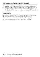
Replacing the Power-Button Module WARNING: Before working inside your computer, read the safety information that shipped with your computer and follow the steps in "Before You Begin" on page 7. After working inside your computer, follow the instructions in "After Working Inside Your Computer" on page 9. For more safety best practices, see the Regulatory Compliance home page at dell.com/regulatory_compliance. Procedure 1 Align and push the power-button module tabs into the slots on the front panel. 2 Align the power-button module cable on the routing guides on the chassis. 3 Connect the power button module cable to the system board connector (LEDH1). See "System-Board Components" on page 11. Postrequisites 1 Replace the drive cage. See "Removing the Drive Cage" on page 26. 2 Replace the front bezel. See "Replacing the Front Bezel" on page 25. 3 Replace the fan shroud. See "Removing the Fan Shroud" on page 14. 4 Replace the computer cover. See "Replacing the Computer Cover" on page 13. 38 | Replacing the Power-Button Module
-
 1
1 -
2
-
3
-
4
-
5
-
6
-
7
-
8
-
9
-
10
-
11
-
12
-
13
-
14
-
15
-
16
-
17
-
18
-
19
-
20
-
21
-
22
-
23
-
24
-
25
-
26
-
27
-
28
-
29
-
30
-
31
-
32
-
 33
33 -
 34
34 -
 35
35 -
 36
36 -
 37
37 -
 38
38 -
 39
39 -
 40
40 -
 41
41 -
 42
42 -
 43
43 -
44
-
45
-
46
-
47
-
48
-
49
-
50
-
51
-
52
 |
 |