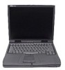
Dell Latitude CPt S Service Manual - Page 11
The illustrations in the following removal procedures provide the correct screw - latitude cpx service manual
 |
View all Dell Latitude CPt S manuals
Add to My Manuals
Save this manual to your list of manuals |
Page 11 highlights
8. Remove the main battery from the battery bay. Slide the battery bay latch toward the right side of the computer. Then slide the battery out of the battery bay (see Figure 2). battery bay latch battery 9. Remove the secondary battery assembly (if present) from the modular bay. 10. Ground yourself by touching the unpainted metal surface of the I/O panel on the back of the computer. While you work, periodically touch the I/O panel to dissipate any static electricity that might harm components. The illustrations in the following removal procedures provide the correct screw length as part of the screw's label. A graphic for that length screw is also included in the illustration. Examples are shown in Figure 3. Match the actual screw to the graphic in the illustration to check for correct length. M2.5x20 M2.5x10 M3.0x5 M2.5x4 M2.5x4 M3.0x3 M2.0x3 support.dell.com Dell Latitude CPt V/CPt S Series and CPx H/CPx J Series Service Manual 3
-
 1
1 -
2
-
3
-
4
-
5
-
 6
6 -
 7
7 -
 8
8 -
 9
9 -
 10
10 -
 11
11 -
 12
12 -
 13
13 -
 14
14 -
 15
15 -
 16
16 -
17
-
18
-
19
-
20
-
21
-
22
-
23
-
24
-
25
-
26
-
27
-
28
-
29
-
30
-
31
-
32
-
33
-
34
-
35
-
36
-
37
-
38
-
39
-
40
-
41
-
42
-
43
-
44
-
45
-
46
-
47
-
48
-
49
-
50
 |
 |
