Dell Latitude CPt S Service Manual - Page 23
and lift the right edge of the keyboard.
 |
View all Dell Latitude CPt S manuals
Add to My Manuals
Save this manual to your list of manuals |
Page 23 highlights
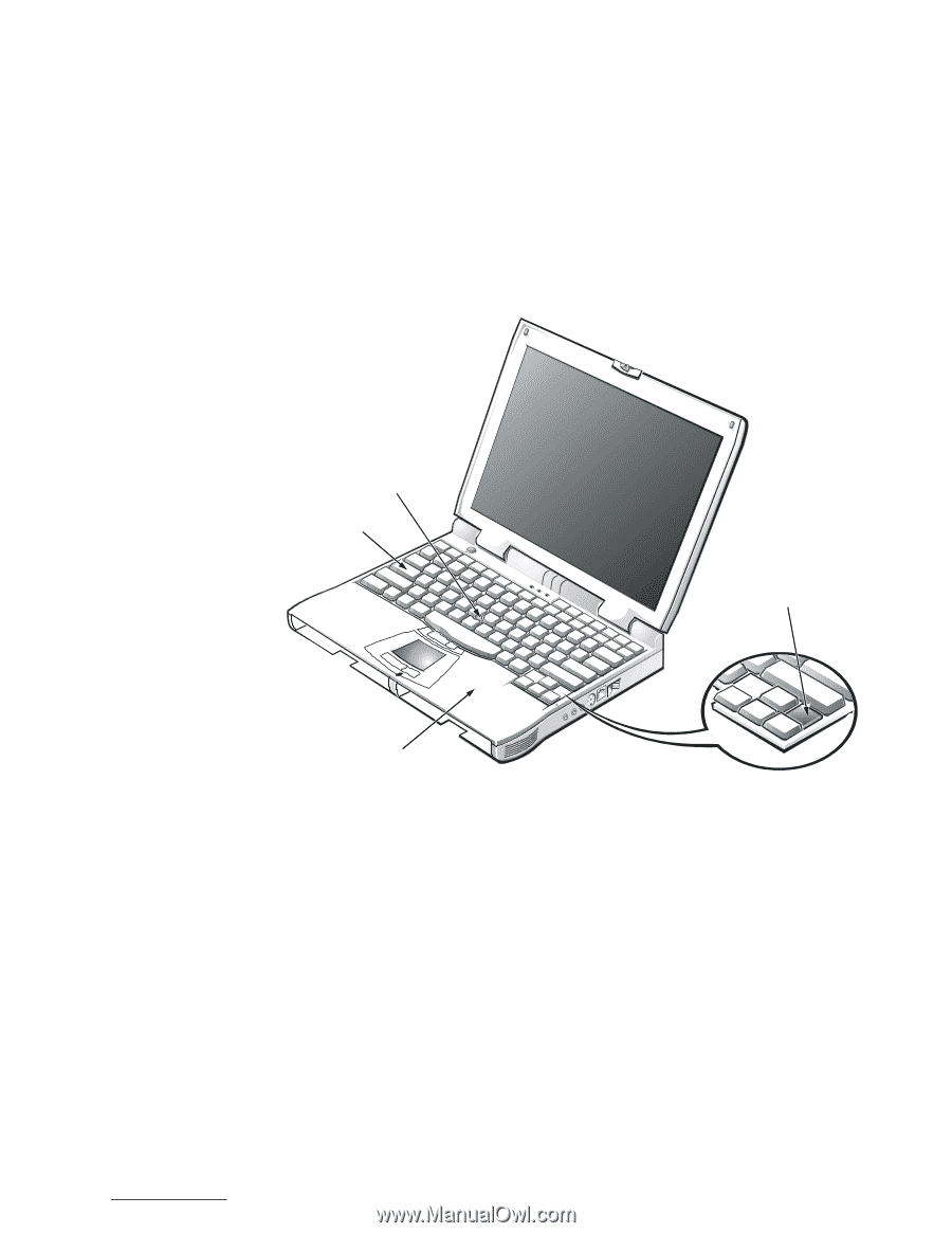
3. Remove the seven 10-mm screws, labeled with a "circle K," that secure the keyboard to the computer (see Figure 9). 4. Turn the computer right-side up and open the display. 5. Release the keyboard from the palmrest assembly by inserting a small flat-blade screwdriver under the edge of the blank key (see Figure 10), and lift the right edge of the keyboard. track stick keyboard scalloped edge of blank key palmrest 6. Lift the keyboard out of the palmrest. 7. Rotate the keyboard over the left edge of the computer (see Figure 11). 8. Rest the key face of the keyboard on the left side of the computer. support.dell.com Dell Latitude CPt V/CPt S Series and CPx H/CPx J Series Service Manual 15
-
 1
1 -
2
-
3
-
4
-
5
-
6
-
7
-
8
-
9
-
10
-
11
-
12
-
13
-
14
-
15
-
16
-
17
-
 18
18 -
 19
19 -
 20
20 -
 21
21 -
 22
22 -
 23
23 -
 24
24 -
 25
25 -
 26
26 -
 27
27 -
 28
28 -
29
-
30
-
31
-
32
-
33
-
34
-
35
-
36
-
37
-
38
-
39
-
40
-
41
-
42
-
43
-
44
-
45
-
46
-
47
-
48
-
49
-
50
 |
 |
support.dell.com
Dell Latitude CPt V/CPt S Series and CPx H/CPx J Series Service Manual
15
3.
Remove the seven 10-mm screws, labeled with a
“
circle K,
”
that secure
the keyboard to the computer (see Figure 9).
4.
Turn the computer right-side up and open the display.
±²³´µ¶·¸³ÂÀ¸(À˽¾ÄÁ¸Å»¸¿ÂÀ¸(ÀËΞü¸¾ÃÀ¸ÊþȺÆÀ"¸À¾ÁºÆ˸¼ºÁÆżÈÀ¼"¸
¾»¼¸¿ºÇÀ&½Å»ÁÌǺ»È¸¿Å¸ÃÀÄƾ½Àϸ5À¸½¾ÃÀÊÌƸÉÂÀ»¸ÃÀÇÅͺ»È¸¾»¼¸
¾»¼Æº»È¸¿ÂÀ¸(ÀËΞüÏ
5.
Release the keyboard from the palmrest assembly by inserting a small
flat-blade screwdriver under the edge of the blank key (see Figure 10),
and lift the right edge of the keyboard.
±²³´µ¶·¸7¹··6¶Å!»ÁµÎ·)%%¶¼!Èŷƶ¼»ÇÁÈ
6.
Lift the keyboard out of the palmrest.
7.
Rotate the keyboard over the left edge of the computer (see Figure 11).
8.
Rest the key face of the keyboard on the left side of the computer.
keyboard
scalloped edge
of blank key
palmrest
track stick