Dell Latitude D620 Service Manual - Page 36
System Board - hard drive replacement
 |
UPC - 837654219218
View all Dell Latitude D620 manuals
Add to My Manuals
Save this manual to your list of manuals |
Page 36 highlights
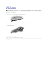
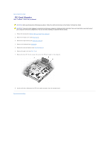
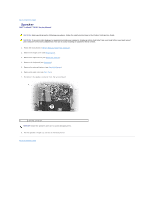
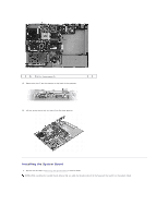
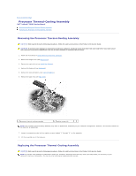
Back to Contents Page System Board Dell™ Latitude™ D620 Service Manual Removing the System Board Installing the System Board Removing the System Board CAUTION: Before performing the following procedures, follow the safety instructions in the Product Information Guide. CAUTION: To prevent static damage to components inside your computer, discharge static electricity from your body before you touch any of your computer's electronic components. You can do so by touching an unpainted metal surface. The system board's BIOS chip contains the Service Tag, which is also visible on a barcode label on the bottom of the computer. The replacement kit for the system board includes a CD that provides a utility for transferring the Service Tag to the replacement system board. 1. Follow the instructions in Before Working Inside Your Computer. 2. Remove the hinge cover (see Hinge Cover). 3. Remove the keyboard (see Keyboard). 4. Remove the display assembly (see Display Assembly). 5. Remove the hard drive (see Hard Drive). 6. Remove the optical drive (see Media Bay Devices). 7. Remove the memory module (see Memory). 8. Remove and installed wireless communications cards (see Communications Cards). 9. Remove the palm rest (see Palm Rest). 10. Remove the modem (see Modem). 11. Remove the speaker (see Speaker). 12. Remove the PC Card reader (see PC Card Reader). 13. Remove the processor thermal-cooling assembly (see Processor Thermal-Cooling Assembly). 14. Remove the processor (see Processor Module). 15. Remove the microphone (see Microphone.) 16. Disconnect the fan cable from the system board. 17. Disconnect the cables near the WLAN card and the modem connector from the system board. 18. Remove the three M2.5 x 5-mm system board screws from the bottom of the computer.
-
 1
1 -
2
-
3
-
4
-
5
-
6
-
7
-
8
-
9
-
10
-
11
-
12
-
13
-
14
-
15
-
16
-
17
-
18
-
19
-
20
-
21
-
22
-
23
-
24
-
25
-
26
-
27
-
28
-
29
-
30
-
 31
31 -
 32
32 -
 33
33 -
 34
34 -
 35
35 -
 36
36 -
 37
37 -
 38
38 -
 39
39 -
 40
40 -
 41
41 -
42
-
43
 |
 |
