Dell OptiPlex 210L Quick Reference Guide - Page 11
Mini Tower Computer - Back-Panel Connectors, User's Guide - network adapter
 |
View all Dell OptiPlex 210L manuals
Add to My Manuals
Save this manual to your list of manuals |
Page 11 highlights
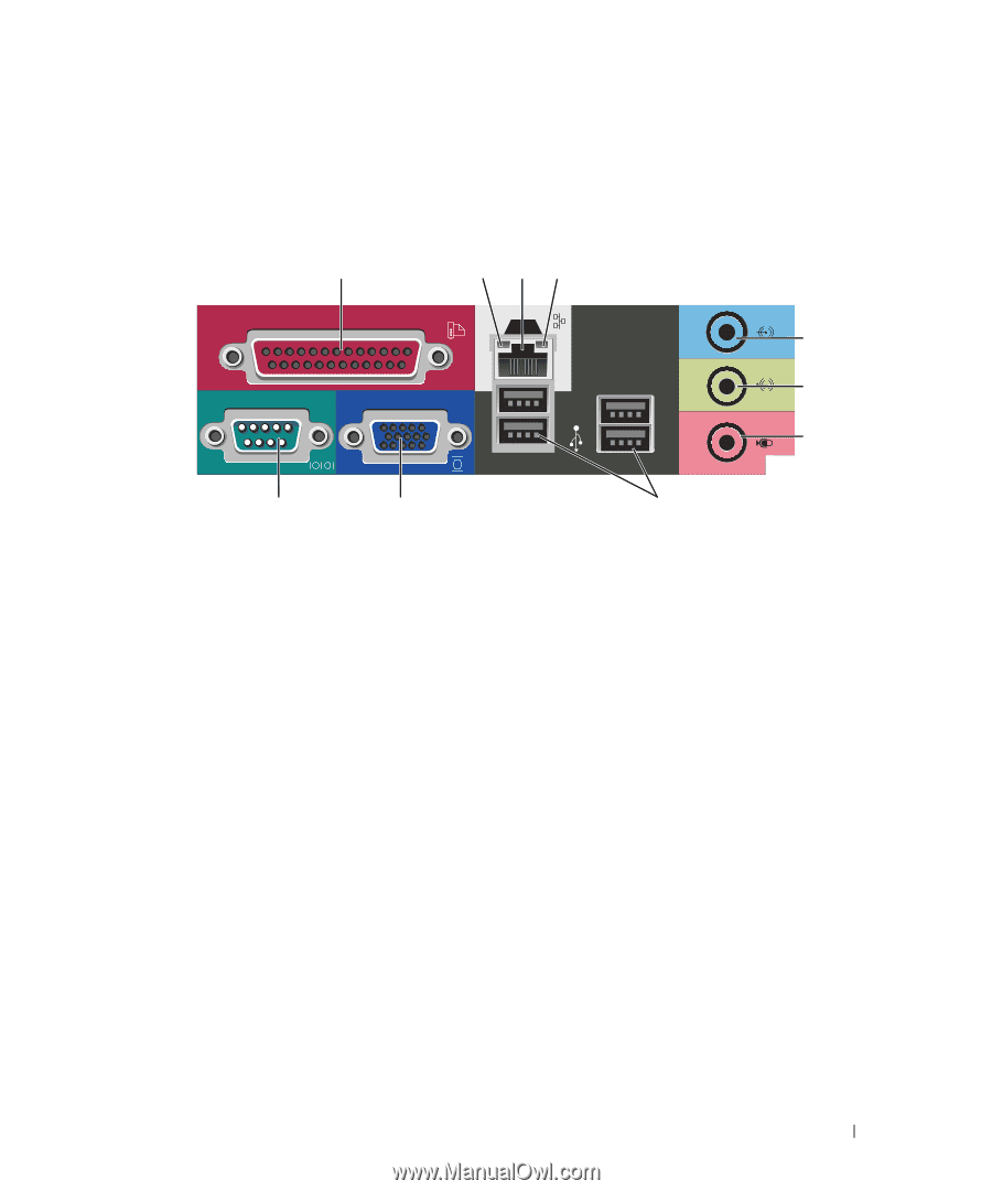
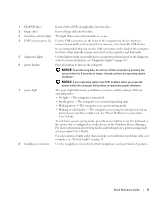
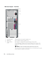
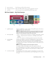
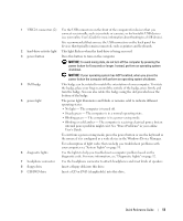
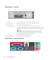
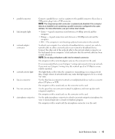
4 power connector Insert the power cable into this connector. 5 back-panel connectors Plug serial, USB, and other devices into the appropriate connector. 6 card slots Access connectors for any installed PCI and PCI Express cards. Mini Tower Computer - Back-Panel Connectors 1 2 34 5 6 7 10 9 8 1 parallel connector 2 link integrity light 3 network adapter connector 4 network activity light Connect a parallel device, such as a printer, to the parallel connector. If you have a USB printer, plug it into a USB connector. NOTE: The integrated parallel connector is automatically disabled if the computer detects an installed card containing a parallel connector configured to the same address. For more information, see your online User's Guide. • Green - A good connection exists between a 10-Mbps network and the computer. • Orange - A good connection exists between a 100-Mbps network and the computer. • Off - The computer is not detecting a physical connection to the network. To attach your computer to a network or broadband device, connect one end of a network cable to either a network jack or your network or broadband device. Connect the other end of the network cable to the network adapter connector on the back panel of your computer. A click indicates that the network cable has been securely attached. NOTE: Do not plug a telephone cable into the network connector. On computers with a network adapter card, use the connector on the card. It is recommended that you use Category 5 wiring and connectors for your network. If you must use Category 3 wiring, force the network speed to 10 Mbps to ensure reliable operation. This light flashes yellow when the computer is transmitting or receiving network data. A high volume of network traffic may make this light appear to be in a steady "on" state. Quick Reference Guide 11
-
 1
1 -
2
-
3
-
4
-
5
-
 6
6 -
 7
7 -
 8
8 -
 9
9 -
 10
10 -
 11
11 -
 12
12 -
 13
13 -
 14
14 -
 15
15 -
 16
16 -
17
-
18
-
19
-
20
-
21
-
22
-
23
-
24
-
25
-
26
-
27
-
28
-
29
-
30
-
31
-
32
-
33
-
34
-
35
-
36
-
37
-
38
-
39
-
40
-
41
-
42
-
43
-
44
-
45
-
46
-
47
-
48
-
49
-
50
-
51
-
52
-
53
-
54
-
55
-
56
-
57
-
58
-
59
-
60
-
61
-
62
-
63
-
64
-
65
-
66
-
67
-
68
-
69
-
70
-
71
-
72
-
73
-
74
-
75
-
76
-
77
-
78
-
79
-
80
-
81
-
82
-
83
-
84
-
85
-
86
-
87
-
88
-
89
-
90
-
91
-
92
-
93
-
94
-
95
-
96
-
97
-
98
-
99
-
100
-
101
-
102
-
103
-
104
-
105
-
106
-
107
-
108
-
109
-
110
-
111
-
112
-
113
-
114
-
115
-
116
-
117
-
118
-
119
-
120
-
121
-
122
-
123
-
124
-
125
-
126
-
127
-
128
 |
 |