Dell PowerConnect 2224 User's Guide - Page 11
Mounting Kit Instructions, Installing the Switch on a Flat Surface
 |
View all Dell PowerConnect 2224 manuals
Add to My Manuals
Save this manual to your list of manuals |
Page 11 highlights
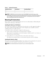
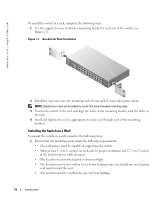
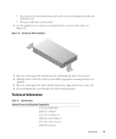
Table 1-1. Tag-Based Prioritization IEEE 802.1p Priority 0-3 4-7 Priority Queue 0 1 Scheduling Weight 1 2 NOTE: The IEEE 802.1p priority information is part of the IEEE 802.1q tag that also defines VLAN memberships. The switches will ignore the VLAN membership information in the tag (that is, all ports are part of all VLANs), but will preserve the full tag information-including packet priority and VLAN ID- when transmitting the packet at the destination port. Mounting Kit Instructions These switches come with mounting brackets and screws for rackmounting or wallmounting and rubber feet for stationing on a flat surface. Installing the Switch on a Flat Surface The switch can be installed on any appropriate level surface that can safely support the weight of the switches and their attached cables. There must be adequate space around the switch for ventilation and access to cable connectors. To install the switch on a flat surface, complete the following steps: 1 Set the switch on the flat surface and check for proper ventilation. Allow at least 5.1 cm (2 inches) on each side for proper ventilation and 12.7 cm (5 inches) at the back for power cable clearance. 2 Attach rubber feet on each marked location on the bottom of the chassis. The rubber feet are optional, but are recommended to keep the switch from slipping. Installing the Switch in a Rack The switch can be installed in Dell PowerEdge™ racks, which are 48.3 cm (19 inches). It can also be installed in most other standard 19-inch racks and most telco two-post racks. NOTE: Do not install rubber feet on the switch if you are rackmounting the switch. Introduction 11
-
 1
1 -
2
-
3
-
4
-
5
-
 6
6 -
 7
7 -
 8
8 -
 9
9 -
 10
10 -
 11
11 -
 12
12 -
 13
13 -
 14
14 -
 15
15 -
 16
16 -
17
-
18
-
19
-
20
-
21
-
22
-
23
-
24
-
25
-
26
-
27
-
28
-
29
-
30
-
31
-
32
-
33
-
34
-
35
-
36
-
37
-
38
 |
 |