Dell PowerConnect 2224 User's Guide - Page 12
Installing the Switch on a Wall, at the back for power cable clearance.
 |
View all Dell PowerConnect 2224 manuals
Add to My Manuals
Save this manual to your list of manuals |
Page 12 highlights
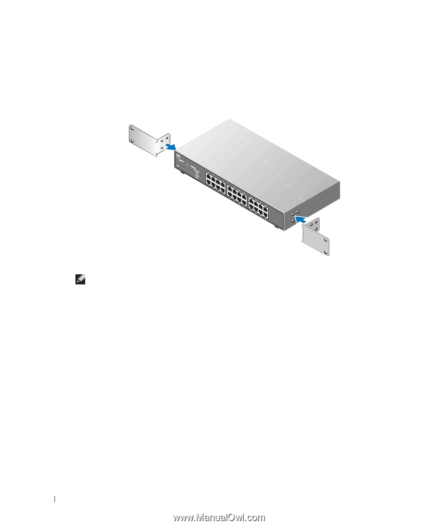
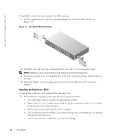
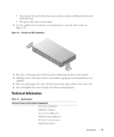
www.dell.com | support.dell.com To install the switch in a rack, complete the following steps: 1 Use the supplied screws to attach a mounting bracket to each side of the switch (see Figure 1-7). Figure 1-7. Brackets for Rack Installation 2 Install the cage nuts onto the mounting rails of your rack, if your rack requires them. NOTE: Additional screws are provided for racks that have threaded mounting holes. 3 Position the switch in the rack and align the holes in the mounting bracket with the holes in the rack. 4 Insert and tighten two screws appropriate for your rack through each of the mounting brackets. Installing the Switch on a Wall To mount the switch on a wall, complete the following steps: 1 Ensure that the mounting point meets the following requirements: • The wall surface must be capable of supporting the switch. • Allow at least 5.1 cm (2 inches) on each side for proper ventilation and 12.7 cm (5 inches) at the back for power cable clearance. • The location must not be located in direct sunlight. • The location must not be within 2 feet of any heating vents, nor should any area heating vent point toward the unit. • The location must be ventilated to prevent heat buildup. 12 Introduction
-
 1
1 -
2
-
3
-
4
-
5
-
6
-
 7
7 -
 8
8 -
 9
9 -
 10
10 -
 11
11 -
 12
12 -
 13
13 -
 14
14 -
 15
15 -
 16
16 -
 17
17 -
18
-
19
-
20
-
21
-
22
-
23
-
24
-
25
-
26
-
27
-
28
-
29
-
30
-
31
-
32
-
33
-
34
-
35
-
36
-
37
-
38
 |
 |