Dell PowerConnect 6248P Getting Started Guide - Page 13
Booting the Switch
 |
View all Dell PowerConnect 6248P manuals
Add to My Manuals
Save this manual to your list of manuals |
Page 13 highlights
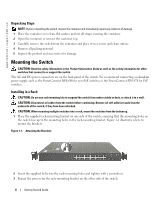
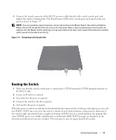
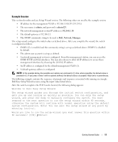
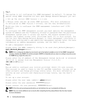
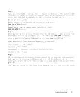
3 Connect the female connector of the RS-232 crossover cable directly to the switch console port, and tighten the captive retaining bolts. The PowerConnect 6200 series console ports are located on the rear panel as shown in Figure 1-4. NOTE: If you are installing a stack of switches, connect the terminal to the Master Switch. This switch will light the Master Switch LED, the top left LED in the array on the front panel. When a stack is powered up for the first time, the switches elect the Master Switch, which may occupy any location in the stack. If you connect the terminal to a member switch, you will not be able to use the CLI. Figure 1-4. Connecting to the Console Port Booting the Switch 1 Make sure that the switch console port is connected to a VT100 terminal or VT100 terminal emulator via the RS-232 cable. 2 Locate an AC power receptacle. 3 Deactivate the AC power receptacle. 4 Connect the switch to the AC receptacle. 5 Activate the AC power receptacle. When the power is turned on with the local terminal already connected, the switch goes through a power-on selftest (POST). POST runs every time the switch is initialized and checks hardware components to determine if the switch is fully operational before completely booting. If POST detects a critical problem, the program flow stops. If POST passes successfully, valid firmware is loaded into RAM. POST messages are displayed on the terminal and indicate test success or failure. The boot process runs for approximately 60 seconds. Getting Started Guide 11
-
 1
1 -
2
-
3
-
4
-
5
-
6
-
7
-
 8
8 -
 9
9 -
 10
10 -
 11
11 -
 12
12 -
 13
13 -
 14
14 -
 15
15 -
 16
16 -
 17
17 -
 18
18 -
19
-
20
-
21
-
22
-
23
-
24
-
25
-
26
-
27
-
28
-
29
-
30
-
31
-
32
-
33
-
34
-
35
-
36
-
37
-
38
-
39
-
40
-
41
-
42
-
43
-
44
-
45
-
46
-
47
-
48
-
49
-
50
-
51
-
52
-
53
-
54
-
55
-
56
-
57
-
58
-
59
-
60
-
61
-
62
-
63
-
64
-
65
-
66
-
67
-
68
-
69
-
70
-
71
-
72
-
73
-
74
-
75
-
76
-
77
-
78
-
79
-
80
-
81
-
82
-
83
-
84
-
85
-
86
-
87
-
88
-
89
-
90
-
91
-
92
-
93
-
94
-
95
-
96
-
97
-
98
-
99
-
100
-
101
-
102
-
103
-
104
-
105
-
106
-
107
-
108
-
109
-
110
-
111
-
112
-
113
-
114
-
115
-
116
-
117
-
118
-
119
-
120
-
121
-
122
-
123
-
124
-
125
-
126
-
127
-
128
-
129
-
130
-
131
-
132
-
133
-
134
-
135
-
136
-
137
-
138
-
139
-
140
-
141
-
142
-
143
-
144
-
145
-
146
-
147
-
148
-
149
-
150
-
151
-
152
-
153
-
154
-
155
-
156
-
157
-
158
-
159
-
160
-
161
-
162
-
163
-
164
-
165
-
166
-
167
-
168
-
169
-
170
-
171
-
172
-
173
-
174
-
175
-
176
-
177
-
178
-
179
-
180
-
181
-
182
-
183
-
184
-
185
-
186
-
187
-
188
-
189
-
190
-
191
-
192
-
193
-
194
-
195
-
196
-
197
-
198
-
199
-
200
-
201
-
202
-
203
-
204
-
205
-
206
-
207
-
208
-
209
-
210
-
211
-
212
-
213
-
214
-
215
-
216
-
217
-
218
-
219
-
220
-
221
-
222
-
223
-
224
-
225
-
226
-
227
-
228
-
229
-
230
-
231
-
232
-
233
-
234
-
235
-
236
-
237
-
238
-
239
-
240
-
241
-
242
-
243
-
244
-
245
-
246
-
247
-
248
-
249
-
250
-
251
-
252
-
253
-
254
-
255
-
256
-
257
-
258
-
259
-
260
-
261
-
262
-
263
-
264
-
265
-
266
-
267
-
268
-
269
-
270
-
271
-
272
-
273
-
274
-
275
-
276
-
277
-
278
-
279
-
280
-
281
-
282
 |
 |
