Dell PowerConnect B-RX Getting Started Guide
Dell PowerConnect B-RX Manual
 |
View all Dell PowerConnect B-RX manuals
Add to My Manuals
Save this manual to your list of manuals |
Dell PowerConnect B-RX manual content summary:
- Dell PowerConnect B-RX | Getting Started Guide - Page 1
53-1001682-03 July 7, 2010 PowerConnect™ B-RX Series Getting Started Guide 53-1001682-03 *53-1001682-03* - Dell PowerConnect B-RX | Getting Started Guide - Page 2
document to refer to either the entities claiming the marks and names or their products Dell Inc. disclaims any proprietary interest in trademarks and trade names other than its own. Regulatory Models: BI-RX-4, BI-RX-8, and BI-RX-16. 2 PowerConnect B-RX Series Getting Started Guide 53-1001682-03 - Dell PowerConnect B-RX | Getting Started Guide - Page 3
, refer to your hardware installation guide. • For rack-specific installation instructions, refer to the appropriate rack mount installation procedures. The PowerConnect B-RX series consists of the following chassis models: • Four-slot chassis, which provides four interface slots • Eight-slot - Dell PowerConnect B-RX | Getting Started Guide - Page 4
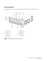
slot 2 3 Switch fabric slot 3 4 ESD connector 5 Interface slot 1 6 Switch fabric slot 1 7 Interface slot 3 8 Management slot 1 9 Management slot 2 10 Interface slot 4 11 Fan tray assembly FIGURE 1 PowerConnect B-RX Series four-slot chassis 4 PowerConnect B-RX Series Getting Started Guide 53 - Dell PowerConnect B-RX | Getting Started Guide - Page 5
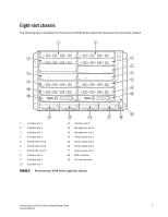
illustrates the PowerConnect B-RX Series eight-slot chassis and components location. 1 2 3 4 5 6 7 9 8 10 11 13 12 14 15 16 1 Interface slot 1 2 Interface slot 2 3 Interface slot 3 4 Interface slot 4 5 Switch fabric slot 1 6 Switch fabric slot 2 7 Switch fabric slot - Dell PowerConnect B-RX | Getting Started Guide - Page 6
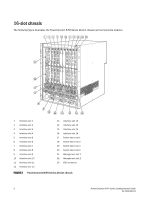
slot 15 16 Interface slot 16 17 Switch fabric slot 1 18 Switch fabric slot 2 19 Switch fabric slot 3 20 Switch fabric slot 4 21 Management slot 1 22 Management slot 2 23 ESD connector FIGURE 3 PowerConnect B-RX Series-16-slot chassis 6 PowerConnect B-RX Series Getting Started Guide 53-1001682 - Dell PowerConnect B-RX | Getting Started Guide - Page 7
your PowerConnect supplier. Installation instructions are provided with the rack kit. This section describes items shipped with the PowerConnect B-RX series and items you will need for installation. Items shipped with units The chassis ships with the following components installed: • Switch fabric - Dell PowerConnect B-RX | Getting Started Guide - Page 8
supplies" on page 20, "Attaching a management station" on page 24, and "Connecting the PowerConnect B-RX Series to a network device" on page 31. Installation location Before installing the switch, plan its location and orientation relative to other devices and equipment. For cooling purposes, allow - Dell PowerConnect B-RX | Getting Started Guide - Page 9
to the PowerConnect B-RX Series. General precautions DANGER The procedures in this manual are for qualified service personnel. run the chassis with an uncovered slot, the system may overheat. CAUTION Never leave tools inside the chassis. PowerConnect B-RX Series Getting Started Guide 9 53-1001682 - Dell PowerConnect B-RX | Getting Started Guide - Page 10
appropriate circuit device, depending on the number of AC power supplies installed in the chassis. DANGER Disconnect the power cord from all power sources to completely remove power from and progressively place lighter devices above. 10 PowerConnect B-RX Series Getting Started Guide 53-1001682-03 - Dell PowerConnect B-RX | Getting Started Guide - Page 11
access area is where access can be gained only by service personnel through the use of a special tool, lock an agency-approved crimp connector (provided on the PowerConnect B-RX Series chassis), crimped with the proper tool. The single PowerConnect B-RX Series Getting Started Guide 11 53-1001682-03 - Dell PowerConnect B-RX | Getting Started Guide - Page 12
or 16-slot chassis by yourself. Using a mechanical lift to maneuver the switch into a rack is recommended. If a lift cannot be used, a minimum of four people must lift the switch, and you must remove components from the chassis before lifting. 12 PowerConnect B-RX Series Getting Started Guide 53 - Dell PowerConnect B-RX | Getting Started Guide - Page 13
. The mid-mount kit comes with instructions for installing the mounting brackets and mounting the device in a rack. Preparing to mount a chassis in a rack Because of the weight of a fully loaded PowerConnect B-RX Series chassis, Dell recommends mounting a chassis in a rack before installing the - Dell PowerConnect B-RX | Getting Started Guide - Page 14
brackets as shown in Figure 6 (four-slot and eight-slot chassis) or Figure 7 (16-slot chassis). Do not secure the screws completely; leave approximately (.635 cm (1/4 in.) of clearance between the back of the screw head and the rack. 14 PowerConnect B-RX Series Getting Started Guide 53-1001682-03 - Dell PowerConnect B-RX | Getting Started Guide - Page 15
more people lifting the chassis, slip the wide portion of each keyhole slot over the corresponding screw in the rack. 1 1 Standard 19 inch rack FIGURE 6 Mounting the PowerConnect B-RX Series four-slot or eight-slot chassis in a rack PowerConnect B-RX Series Getting Started Guide 15 53-1001682-03 - Dell PowerConnect B-RX | Getting Started Guide - Page 16
to install the PowerConnect B-RX Series management module in another Dell chassis or a management module intended for another Dell chassis in the PowerConnect B-RX Series chassis, the chassis and module will not function properly. 16 PowerConnect B-RX Series Getting Started Guide 53-1001682-03 - Dell PowerConnect B-RX | Getting Started Guide - Page 17
screwdriver. Follow the steps given below to install a module in the PowerConnect B-RX Series chassis. NOTE The installation instructions for installing modules in the following steps are exactly the same for interface, management, and switch fabric modules. 1. Put on the ESD wrist strap and ground - Dell PowerConnect B-RX | Getting Started Guide - Page 18
1 1 Interface module FIGURE 8 Installing a module in a PowerConnect B-RX Series four-slot chassis 1 1 Management module FIGURE 9 Installing a module in a PowerConnect B-RX Series eight-slot chassis 18 PowerConnect B-RX Series Getting Started Guide 53-1001682-03 - Dell PowerConnect B-RX | Getting Started Guide - Page 19
the flat-head screwdriver. Rules for populating a PowerConnect B-RX Series-16 chassis 1. Install a management module in management slot 2. 2. Install interface modules in interface slots 2, 4, 6, and 8. 3. Install switch fabric modules in the switch fabric slots 2 and 4. 4. Install interface modules - Dell PowerConnect B-RX | Getting Started Guide - Page 20
16-slot chassis with four additional power supplies provides full redundancy for all of the required power supplies. Follow the steps given below to install a power supply in the PowerConnect B-RX Series chassis the guides. Never insert the power supply upside down. 4. For the four-slot chassis, - Dell PowerConnect B-RX | Getting Started Guide - Page 21
power supply in a PowerConnect B-RX Series four-slot chassis 5. For the eight-slot and 16-slot chassis, follow these steps while referring to Figure 12 or Figure 13 on page 22 (depending on your chassis), then continue with step 6. a. Slide the card along the card guide until fully inserted, then - Dell PowerConnect B-RX | Getting Started Guide - Page 22
in a PowerConnect B-RX Series 16-slot chassis 6. For information about connecting power to the chassis, refer to PowerConnect B-RX Series chassis. 1. Locate the power receptacle on the rear of the chassis, behind where AC power supplies are installed. 2. Lift the cord-retainer and connect a Dell - Dell PowerConnect B-RX | Getting Started Guide - Page 23
for the PowerConnect B-RX Series chassis. This is supported through use of a DC-to-DC power supply. DC power must be supplied at 48 V and 30 A. The DC-to-DC supply provides the DC power to the chassis at 12 V and 100 A. DANGER The procedure in this section is for qualified service personnel. Follow - Dell PowerConnect B-RX | Getting Started Guide - Page 24
power supply wire FIGURE 16 Crimping the power cables attached to PowerConnect B-RX Series, refer to the chapter in your hardware installation guide on using the You can connect the PowerConnect B-RX Series switch to your existing management network and manage the switch, along with other network - Dell PowerConnect B-RX | Getting Started Guide - Page 25
module slots are uncovered. CAUTION If you do not install a module in a slot, you must keep the slot blank in place. If you run the chassis with an uncovered slot, the system may overheat. PowerConnect B-RX Series Getting Started Guide 25 53-1001682-03 - Dell PowerConnect B-RX | Getting Started Guide - Page 26
B-RX Series chassis powers on, you can observe its LEDs to verify that it initialized successfully. Refer to your hardware installation guide for a complete description of the LEDs. If a problem persists after taking action described in this table, contact technical support. 26 PowerConnect B-RX - Dell PowerConnect B-RX | Getting Started Guide - Page 27
or terminal to the management module's Console port or Ethernet port and the PowerConnect B-RX Series switch has initialized successfully, press Enter to display the following CLI prompt in the terminal emulation window: BigIron RX> If you do not see this prompt, do the following. 1. Make sure the - Dell PowerConnect B-RX | Getting Started Guide - Page 28
password using the Web management interface. You can assign passwords using the switch's Network Manager if an Enable password for a Super User is RX(config)# enable port-config-password BigIron RX(config)# enable read-only-password 28 PowerConnect B-RX Series Getting Started Guide - Dell PowerConnect B-RX | Getting Started Guide - Page 29
interface or virtual interface over which user packets are routed Support of sub-net masks The PowerConnect B-RX Series switch supports both classical IP network masks (Class A, B, and CLI prompt, enter enable. BigIron RX> enable PowerConnect B-RX Series Getting Started Guide 29 53-1001682-03 - Dell PowerConnect B-RX | Getting Started Guide - Page 30
the CLI through Telnet or the Web management interface. You can use the switch's Network Manager to assign IP addresses to virtual routing interfaces only. By default command: BigIron RX# configure terminal BigIron RX(config)# 30 PowerConnect B-RX Series Getting Started Guide 53-1001682-03 - Dell PowerConnect B-RX | Getting Started Guide - Page 31
-if-mgmt-1)# disable Connecting the PowerConnect B-RX Series to a network device You can connect a PowerConnect B-RX Series switch to another 10 Gigabit Ethernet network device. The PowerConnect B-RX Series switch supports connections to other vendors' as well as Dell devices. The 10 Gigabit - Dell PowerConnect B-RX | Getting Started Guide - Page 32
To connect a PowerConnect B-RX Series switch to another network device, you must do the following: • Install the fiber optic modules • Cable the fiber optic modules Refer to your hardware installation guide for information about performing these tasks as well as cleaning the fiber optic connectors
-
 1
1 -
 2
2 -
 3
3 -
 4
4 -
 5
5 -
 6
6 -
 7
7 -
8
-
9
-
10
-
11
-
12
-
13
-
14
-
15
-
16
-
17
-
18
-
19
-
20
-
21
-
22
-
23
-
24
-
25
-
26
-
27
-
28
-
29
-
30
-
31
-
32
 |
 |

53-1001682-03
July 7, 2010
53-1001682-03
*53-1001682-03*
PowerConnect™ B-RX
Series
Getting Started Guide