Dell PowerConnect B-RX Getting Started Guide - Page 3

In this guide, Introduction - powerconnect h e b rx plan

Page 3 highlights

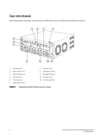
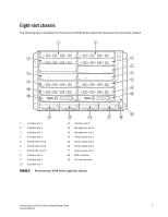
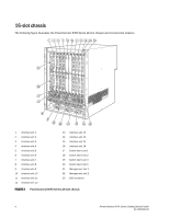
In this guide •Introduction 3 •Four-slot chassis 4 •Eight-slot chassis 5 •Items required for installation 7 •Site planning and safety guidelines 8 •Unpacking the PowerConnect B-RX Series 12 •Chassis lifting guidelines for PowerConnect B-RX Series 12 •Installing a PowerConnect B-RX Series chassis in a rack 13 •Installing modules 16 •Installing power supplies 20 •Connecting AC power 22 •Connecting DC power 23 •Managing cables 24 •Attaching a management station 24 •Powering-on the power source 25 •Verifying proper operation 26 •Assigning passwords 27 •Configuring IP addresses 29 •Connecting the PowerConnect B-RX Series to a network device 31 Introduction This guide provides instructions for unpacking, installing, and setting up PowerConnect B-RX Series four-slot, eight-slot, and 16-slot models in equipment racks. Note the following additional documentation: • For detailed installation and configuration instructions, refer to your hardware installation guide. • For rack-specific installation instructions, refer to the appropriate rack mount installation procedures. The PowerConnect B-RX series consists of the following chassis models: • Four-slot chassis, which provides four interface slots • Eight-slot chassis, which provides eight interface slots • 16-slot chassis, which provides 16 interface slots. The PowerConnect B-RX Series can be installed in the following ways: • In a 19-in. Electronic Industries Association cabinet (EIA310-D). The B-RX Series units have built-in mounting brackets for installing in racks. • In a mid-mount telecommunications (Telco) rack. A mid-mount kit can be ordered separately from your PowerConnect supplier to center mount the PowerConnect unit in the rack. It contains two L-shaped mounting brackets and instructions for installing the brackets and mounting the unit. The basic configuration steps required to set up the PowerConnect B-RX Series are listed in this guide. Additional configuration information is provided in the hardware installation manual. PowerConnect B-RX Series Getting Started Guide 3 53-1001682-03

  • 1
  • 2
  • 3
  • 4
  • 5
  • 6
  • 7
  • 8
  • 9
  • 10
  • 11
  • 12
  • 13
  • 14
  • 15
  • 16
  • 17
  • 18
  • 19
  • 20
  • 21
  • 22
  • 23
  • 24
  • 25
  • 26
  • 27
  • 28
  • 29
  • 30
  • 31
  • 32

PowerConnect B-RX Series Getting Started Guide
3
53-1001682-03
In this guide
Introduction. . . . . . . . . . . . . . . . . . . . . . . . . . . . . . . . . . . . . . . . . . . . . . . . . . . .
3
Four-slot chassis. . . . . . . . . . . . . . . . . . . . . . . . . . . . . . . . . . . . . . . . . . . . . . . .
4
Eight-slot chassis . . . . . . . . . . . . . . . . . . . . . . . . . . . . . . . . . . . . . . . . . . . . . . .
5
Items required for installation . . . . . . . . . . . . . . . . . . . . . . . . . . . . . . . . . . . . .
7
Site planning and safety guidelines . . . . . . . . . . . . . . . . . . . . . . . . . . . . . . . .
8
Unpacking the PowerConnect B-RX Series . . . . . . . . . . . . . . . . . . . . . . . . . .
12
Chassis lifting guidelines for PowerConnect B-RX Series . . . . . . . . . . . . . .
12
Installing a PowerConnect B-RX Series chassis in a rack . . . . . . . . . . . . . .
13
Installing modules . . . . . . . . . . . . . . . . . . . . . . . . . . . . . . . . . . . . . . . . . . . . .
16
Installing power supplies . . . . . . . . . . . . . . . . . . . . . . . . . . . . . . . . . . . . . . . .
20
Connecting AC power . . . . . . . . . . . . . . . . . . . . . . . . . . . . . . . . . . . . . . . . . . .
22
Connecting DC power. . . . . . . . . . . . . . . . . . . . . . . . . . . . . . . . . . . . . . . . . . .
23
Managing cables . . . . . . . . . . . . . . . . . . . . . . . . . . . . . . . . . . . . . . . . . . . . . .
24
Attaching a management station . . . . . . . . . . . . . . . . . . . . . . . . . . . . . . . . .
24
Powering-on the power source . . . . . . . . . . . . . . . . . . . . . . . . . . . . . . . . . . .
25
Verifying proper operation . . . . . . . . . . . . . . . . . . . . . . . . . . . . . . . . . . . . . . .
26
Assigning passwords . . . . . . . . . . . . . . . . . . . . . . . . . . . . . . . . . . . . . . . . . . .
27
Configuring IP addresses. . . . . . . . . . . . . . . . . . . . . . . . . . . . . . . . . . . . . . . .
29
Connecting the PowerConnect B-RX Series to a network device . . . . . . . .
31
Introduction
This guide provides instructions for unpacking, installing, and setting up PowerConnect B-RX Series four-slot,
eight-slot, and 16-slot models in equipment racks. Note the following additional documentation:
For detailed installation and configuration instructions, refer to your hardware installation guide.
For rack-specific installation instructions, refer to the appropriate rack mount installation procedures.
The PowerConnect B-RX series consists of the following chassis models:
Four-slot chassis, which provides four interface slots
Eight-slot chassis, which provides eight interface slots
16-slot chassis, which provides 16 interface slots.
The PowerConnect B-RX Series can be installed in the following ways:
In a 19-in. Electronic Industries Association cabinet (EIA310-D). The B-RX Series units have built-in mounting
brackets for installing in racks.
In a mid-mount telecommunications (Telco) rack. A mid-mount kit can be ordered separately from your
PowerConnect supplier to center mount the PowerConnect unit in the rack. It contains two L-shaped mounting
brackets and instructions for installing the brackets and mounting the unit.
The basic configuration steps required to set up the PowerConnect B-RX Series are listed in this guide. Additional
configuration information is provided in the hardware installation manual.