Dell PowerConnect B-RX Getting Started Guide - Page 5
Eight-slot chassis
 |
View all Dell PowerConnect B-RX manuals
Add to My Manuals
Save this manual to your list of manuals |
Page 5 highlights
Eight-slot chassis The following figure illustrates the PowerConnect B-RX Series eight-slot chassis and components location. 1 2 3 4 5 6 7 9 8 10 11 13 12 14 15 16 1 Interface slot 1 2 Interface slot 2 3 Interface slot 3 4 Interface slot 4 5 Switch fabric slot 1 6 Switch fabric slot 2 7 Switch fabric slot 3 8 Interface slot 5 9 Interface slot 6 10 Interface slot 7 11 Interface slot 8 12 Management slot 1 13 Management slot 2 14 Power supply slot 1 15 Power supply slot 2 16 Power supply slot 3 17 Power supply slot 4 18 ESD connector 19 Fan tray assembly FIGURE 2 PowerConnect B-RX Series eight-slot chassis 19 17 18 PowerConnect B-RX Series Getting Started Guide 5 53-1001682-03
-
 1
1 -
 2
2 -
 3
3 -
 4
4 -
 5
5 -
 6
6 -
 7
7 -
 8
8 -
 9
9 -
 10
10 -
 11
11 -
12
-
13
-
14
-
15
-
16
-
17
-
18
-
19
-
20
-
21
-
22
-
23
-
24
-
25
-
26
-
27
-
28
-
29
-
30
-
31
-
32
 |
 |

PowerConnect B-RX Series Getting Started Guide
5
53-1001682-03
Eight-slot chassis
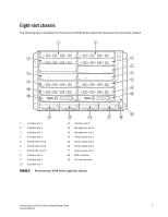
The following figure illustrates the PowerConnect B-RX Series eight-slot chassis and components location.
FIGURE 2
PowerConnect B-RX Series eight-slot chassis
1
Interface slot 1
11
Interface slot 8
2
Interface slot 2
12
Management slot 1
3
Interface slot 3
13
Management slot 2
4
Interface slot 4
14
Power supply slot 1
5
Switch fabric slot 1
15
Power supply slot 2
6
Switch fabric slot 2
16
Power supply slot 3
7
Switch fabric slot 3
17
Power supply slot 4
8
Interface slot 5
18
ESD connector
9
Interface slot 6
19
Fan tray assembly
10
Interface slot 7
8
10
12
6
9
7
5
4
3
14
15
11
16
17
1
2
13
18
19