Dell PowerConnect B-RX Getting Started Guide - Page 8
Site planning and safety guidelines, Site planning - powerconnect plan b rx
 |
View all Dell PowerConnect B-RX manuals
Add to My Manuals
Save this manual to your list of manuals |
Page 8 highlights
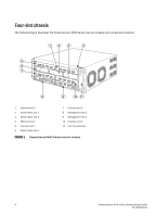
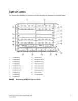
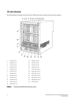
• Eight-slot chassis - Up to two management modules (one active and one redundant). - Up to three switch fabric modules. - Up to eight interface modules. - Up to four power supplies (AC or DC). • 16-slot chassis - Up to two management modules (one active and one redundant). - Up to four switch fabric modules. - Up to 16 interface modules. - Up to eight power supplies (AC or DC). NOTE Before installing any modules or power supplies, you must remove the slot blank or blank power supply faceplate, respectively. Site planning and safety guidelines The following steps and safety precautions are required to ensure correct installation and operation. Site planning Follow these steps to ensure your site is ready for installation. Cabling infrastructure Ensure that the proper cabling is installed in the site. For information on cabling, refer to "Installing power supplies" on page 20, "Attaching a management station" on page 24, and "Connecting the PowerConnect B-RX Series to a network device" on page 31. Installation location Before installing the switch, plan its location and orientation relative to other devices and equipment. For cooling purposes, allow a minimum of 15.24 cm (6 in.) of space between the sides, front, and the back of the chassis and walls or other obstructions. If a chassis is installed within a perforated enclosure, the perforations must have openings of at least 60 percent of the surface. 8 PowerConnect B-RX Series Getting Started Guide 53-1001682-03
-
 1
1 -
2
-
 3
3 -
 4
4 -
 5
5 -
 6
6 -
 7
7 -
 8
8 -
 9
9 -
 10
10 -
 11
11 -
 12
12 -
 13
13 -
14
-
15
-
16
-
17
-
18
-
19
-
20
-
21
-
22
-
23
-
24
-
25
-
26
-
27
-
28
-
29
-
30
-
31
-
32
 |
 |
