Dell PowerConnect Brocade 6505 Hardware Reference Guide - Page 15
Port side of the Brocade 6505 - brocade firmware download
 |
View all Dell PowerConnect Brocade 6505 manuals
Add to My Manuals
Save this manual to your list of manuals |
Page 15 highlights
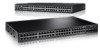
Port side of the Brocade 6505 1 • An RJ45 10/100 BaseT Ethernet system management port, in conjunction with Brocade EZSwitchSetup, that supports switch IP address discovery and configuration, eliminating the need to attach a serial cable to configure the switch IP address and greatly increasing the ease of use. • One RS-232 serial port with an RJ45 connector for initial switch setup (if not using EZSwitchSetup) and factory default restoration. • A USB 2.0 port that provides storage for firmware updates, output of the supportSave command, and storage for configuration uploads and downloads. • One power supply and fan assembly in the base model. There are two fans per assembly. A second assembly is available for redundancy and hot-swap capability. • One LED (green/amber) per FC port to indicate status. • One LED (green) for system power. • One LED (green/amber) for system status. • Two Ethernet port LEDs (integrated with RJ45) for speed and port activity. (A green LED for port speed and an amber LED for port activity.) • SEEPROM for switch identification. • Voltage monitor. • Fan monitor. • Temperature monitor. • Real-time clock (RTC) with battery. Port side of the Brocade 6505 The port side of the Brocade 6505 includes the system status LED, the console port, the Ethernet port and accompanying LEDs, the USB port, and the Fibre Channel ports and corresponding port status LEDs. Figure 1 shows the port side of the Brocade 6505. Brocade 6505 Hardware Reference Manual 3 53-1002449-01
-
 1
1 -
2
-
3
-
4
-
5
-
6
-
7
-
8
-
9
-
 10
10 -
 11
11 -
 12
12 -
 13
13 -
 14
14 -
 15
15 -
 16
16 -
 17
17 -
 18
18 -
 19
19 -
 20
20 -
21
-
22
-
23
-
24
-
25
-
26
-
27
-
28
-
29
-
30
-
31
-
32
-
33
-
34
-
35
-
36
-
37
-
38
-
39
-
40
-
41
-
42
-
43
-
44
-
45
-
46
-
47
-
48
-
49
-
50
-
51
-
52
-
53
-
54
-
55
-
56
-
57
-
58
-
59
-
60
 |
 |
