Dell PowerConnect Brocade 6505 Hardware Reference Guide - Page 20
Cabinet installation for a Brocade 6505, Brocade 6505 configuration, Providing power to the switch
 |
View all Dell PowerConnect Brocade 6505 manuals
Add to My Manuals
Save this manual to your list of manuals |
Page 20 highlights
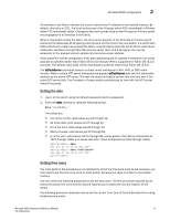
2 Cabinet installation for a Brocade 6505 4. Provide power to the switch as described in "Providing power to the switch" on page 8. ATTENTION Do not connect the switch to the network until the IP address is correctly set. For instructions on how to set the IP address, see "Brocade 6505 configuration." Cabinet installation for a Brocade 6505 Follow the installation instructions shipped with the appropriate rack mount kit: • To install the switch into a fixed-rail rack, refer to the Slim Rail Rack Mount Kit Installation Procedure. • To install the switch into a 2-post Telco rack, refer to the Flush Mount Rack Mount Kit Installation Procedure. Brocade 6505 configuration Once you have set up the Brocade 6505 in a rack or as a standalone switch, it is time to apply power and a basic configuration. If you are going to use the Brocade 6505 in a single-switch setup, you can use EZSwitchSetup to complete the basic configuration. See the EZSwitchSetup CD, included with the Brocade 6505, for more information. You can also use the Brocade 6505 EZSwitchSetup poster. If you do not want to use EZSwitchSetup, continue with the instructions in this section. Providing power to the switch Perform the following steps to provide power to the Brocade 6505. 1. Connect the power cord to the power supply, and then to a power source. If using two power supplies, be sure to connect the cords to power sources on separate circuits to protect against AC failure. Ensure that the cords have a minimum service loop of 6 inches available and are routed to avoid stress. 2. Power on the power supplies by flipping both AC switches to the "I" symbol. The power supply LEDs display amber until power-on self-test (POST) is complete, and then change to green. The switch usually requires several minutes to boot and complete POST. ATTENTION Power is supplied to the switch as soon as the first power supply is connected and turned on. 3. After POST is complete, verify that the switch power and status LEDs on the left of the port side of the switch are green. See Figure 3 for the specific location of the LEDs. Creating a serial connection NOTE You will perform all configuration tasks in this guide using a serial connection. 8 Brocade 6505 Hardware Reference Manual 53-1002449-01
-
 1
1 -
2
-
3
-
4
-
5
-
6
-
7
-
8
-
9
-
10
-
11
-
12
-
13
-
14
-
 15
15 -
 16
16 -
 17
17 -
 18
18 -
 19
19 -
 20
20 -
 21
21 -
 22
22 -
 23
23 -
 24
24 -
 25
25 -
26
-
27
-
28
-
29
-
30
-
31
-
32
-
33
-
34
-
35
-
36
-
37
-
38
-
39
-
40
-
41
-
42
-
43
-
44
-
45
-
46
-
47
-
48
-
49
-
50
-
51
-
52
-
53
-
54
-
55
-
56
-
57
-
58
-
59
-
60
 |
 |
