Dell PowerEdge 2100 Service Manual - Page 51
Computer Cover
 |
View all Dell PowerEdge 2100 manuals
Add to My Manuals
Save this manual to your list of manuals |
Page 51 highlights
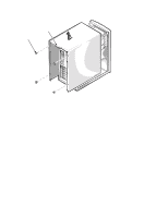
Computer Cover cover-mounting screws (4) handle Figure 4-1. Computer Cover Removal To remove the computer cover, follow these steps: 1. Remove the four cover-mounting screws at the back of the computer. 2. Slide the cover backward about one inch, then grasp the front of the cover and the handle at the back of the cover and lift the cover straight up off the chassis. Removing and Replacing Parts 4-3
-
 1
1 -
2
-
3
-
4
-
5
-
6
-
7
-
8
-
9
-
10
-
11
-
12
-
13
-
14
-
15
-
16
-
17
-
18
-
19
-
20
-
21
-
22
-
23
-
24
-
25
-
26
-
27
-
28
-
29
-
30
-
31
-
32
-
33
-
34
-
35
-
36
-
37
-
38
-
39
-
40
-
41
-
42
-
43
-
44
-
45
-
 46
46 -
 47
47 -
 48
48 -
 49
49 -
 50
50 -
 51
51 -
 52
52 -
 53
53 -
 54
54 -
 55
55 -
 56
56 -
57
-
58
-
59
-
60
-
61
-
62
-
63
-
64
-
65
-
66
-
67
-
68
-
69
-
70
 |
 |

Removing and Replacing Parts
4-3
C
omputer Cover
Figure 4-1.
Computer Cover Removal
To remove the computer cover, follow these steps:
1.
Remove the four cover-mounting screws at the back of the computer.
2.
Slide the cover backward about one inch, then grasp the front of the
cover and the handle at the back of the cover and lift the cover straight
up off the chassis.
cover-mounting
screws (4)
handle