Dell PowerEdge 2100 Service Manual - Page 52
Front Bezel
 |
View all Dell PowerEdge 2100 manuals
Add to My Manuals
Save this manual to your list of manuals |
Page 52 highlights
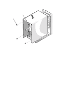
Front Bezel retaining holes (6) retaining clips (6) alignment holes (5) alignment pins (5) Figure 4-2. Front Bezel Removal To remove the front bezel, follow these steps: 1. Remove the computer cover. 2. Pry the front bezel loose with your finger tips and remove it from the chassis. As you pry the front bezel loose, pry at different points around the bezel to keep the opening between the front bezel and the computer chassis equal on all sides to prevent damage to the bezel alignment pins. 4-4 Dell PowerEdge 2100/180 and 2100/200 Systems Service Manual
-
 1
1 -
2
-
3
-
4
-
5
-
6
-
7
-
8
-
9
-
10
-
11
-
12
-
13
-
14
-
15
-
16
-
17
-
18
-
19
-
20
-
21
-
22
-
23
-
24
-
25
-
26
-
27
-
28
-
29
-
30
-
31
-
32
-
33
-
34
-
35
-
36
-
37
-
38
-
39
-
40
-
41
-
42
-
43
-
44
-
45
-
46
-
 47
47 -
 48
48 -
 49
49 -
 50
50 -
 51
51 -
 52
52 -
 53
53 -
 54
54 -
 55
55 -
 56
56 -
 57
57 -
58
-
59
-
60
-
61
-
62
-
63
-
64
-
65
-
66
-
67
-
68
-
69
-
70
 |
 |

4-4
Dell PowerEdge 2100/180 and 2100/200 Systems Service Manual
F
ront Bezel
Figure 4-2.
Front Bezel Removal
To remove the front bezel, follow these steps:
1.
Remove the computer cover.
2.
Pry the front bezel loose with your finger tips and remove it from the
chassis.
As you pry the front bezel loose, pry at different points around the bezel to
keep the opening between the front bezel and the computer chassis equal on
all sides to prevent damage to the bezel alignment pins.
alignment holes (5)
retaining clips (6)
retaining holes (6)
alignment pins (5)