Dell PowerEdge 2400 Installing Redundant Power Supplies - Page 4
Dell PowerEdge 2400 Systems, Installing Redundant Power Supplies, Top cover, Screws 2 - backplane
 |
View all Dell PowerEdge 2400 manuals
Add to My Manuals
Save this manual to your list of manuals |
Page 4 highlights
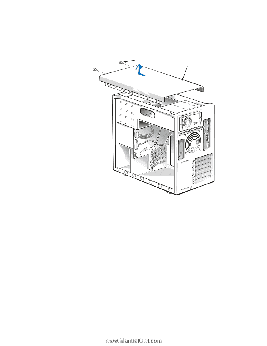
Screws (2) Top cover 4. Slide the top cover about 2 centimeters (cm) (about half an inch) toward the front of the computer and lift the cover away. 5. Disconnect the power cable harness from the POWER connector on the small computer system interface (SCSI) backplane board, the POWER1 connector on the system board, and the diskette drive and other drives in the external drive bays. When you disconnect a cable connector from the SCSI backplane board and the system board, press the plastic latch on one side of the connector to release it. 6. Remove the two screws on either side of the power supply (see Figure 1-2). 1-2 Dell PowerEdge 2400 Systems - Installing Redundant Power Supplies
-
 1
1 -
 2
2 -
 3
3 -
 4
4 -
 5
5 -
 6
6 -
 7
7 -
 8
8
 |
 |
1-2
Dell PowerEdge 2400 Systems
—
Installing Redundant Power Supplies
±²³´µ¶·¸¹¸º··»¶¼½¾²¿³·ÀÁ¶·Â½Ã·Ä½¾¶µ
4.
Slide the top cover about 2 centimeters (cm) (about half an inch) toward the front
of the computer and lift the cover away.
5.
Disconnect the power cable harness from the POWER connector on the small
computer system interface (SCSI) backplane board, the POWER1 connector on
the system board, and the diskette drive and other drives in the external drive
bays.
When you disconnect a cable connector from the SCSI backplane board and the
system board, press the plastic latch on one side of the connector to release it.
6.
Remove the two screws on either side of the power supply (see Figure 1-2).
Top cover
Screws (2)