Dell PowerEdge External Media System 1434 Improving NFS performance on HPC clu - Page 10
I/O clients test bed, Server configuration, Software, Firmware and Drivers
 |
View all Dell PowerEdge External Media System 1434 manuals
Add to My Manuals
Save this manual to your list of manuals |
Page 10 highlights
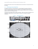
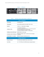
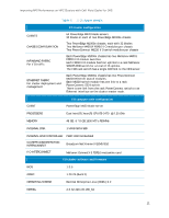
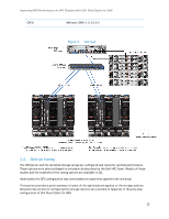
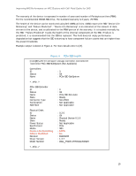
Improving NFS Performance on HPC Clusters with Dell Fluid Cache for DAS Table 3. Hardware configuration for DFC Server configuration NFS SERVER PowerEdge R720 CACHE POOL Two 350GB Dell PowerEdge Express Flash PCIe SSD SSD CONTROLLER Internal (slot 4) Rest of the configuration is the same as baseline, as described in Table 1 Storage configuration Same as baseline, as described in Table 1 Table 4. Software and firmware configuration for DFC Software CACHING SOFTWARE Dell Fluid Cache for DAS v1.0 Rest of the configuration is the same as baseline, as described in Table 2 Firmware and Drivers PCIe SSD DRIVER mtip32xx 1.3.7-1 latest available at the time of this study. Recommend using mtip32xx v2.1.0 Rest of the configuration is the same as baseline, as described in Table 2 In DFC vocabulary, the cache or cache pool is the SSDs, and the disk that is enabled for caching is the virtual disk on the PowerVault MD1200s. Most importantly, the methods used to access the data remain the same as in the baseline case. The I/O clients simply mount the same NFS exported directory as in the baseline configuration. Detailed instructions on configuring DFC for this storage solution are provided in Appendix A: Step-by-step configuration of Dell Fluid Cache for NFS. 2.3. I/O clients test bed The pure NFS baseline solution and the NFS+DFC solution were exercised using a 64-node HPC cluster. This compute cluster was used to provide I/O load to the storage solution and help benchmark the capabilities of the solution. Using the latest quarter height Dell PowerEdge M420 blade server5 as the building block for the I/O cluster, the 64-client cluster was configured in 20U of rack space. Details of the 64-client test bed are provided in Table 5. Figure 3 shows the entire test bed including the clients. Note that all I/O traffic to the NFS server used the InfiniBand network and the IPoIB protocol. 10
-
 1
1 -
2
-
3
-
4
-
 5
5 -
 6
6 -
 7
7 -
 8
8 -
 9
9 -
 10
10 -
 11
11 -
 12
12 -
 13
13 -
 14
14 -
 15
15 -
16
-
17
-
18
-
19
-
20
-
21
-
22
-
23
-
24
-
25
-
26
-
27
-
28
-
29
-
30
-
31
-
32
-
33
-
34
-
35
-
36
-
37
-
38
 |
 |