Dell PowerEdge M420 InfiniScale IV 16+16 Port 40Gb/s InfiniBand Switch for Del - Page 12
Removing an I/O Module Blank From the Chassis
 |
View all Dell PowerEdge M420 manuals
Add to My Manuals
Save this manual to your list of manuals |
Page 12 highlights
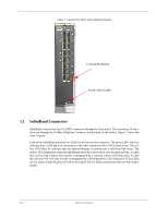
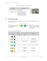
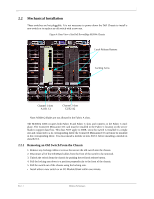
M3601Q 16+16 Port 40Gb/s InfiniBand Switch User Manual 12 2.2.2 Removing an I/O Module Blank From the Chassis 1. Unlock the I/O Module Blank by pushing the red latch release button. 2. Pull the locking arm down to a position perpendicular to the front of the chassis. 3. Pull the I/O Module Blank out of the chassis using the locking arm. 4. Install either a new switch or reinstall a blank IOM within one minute. 2.2.3 Installing the Mellanox M3601Q Switch Into the Dell Chassis Note: Make sure the rack is stable on a solid floor and that the rack is filled from the bottom up. This will keep the center of gravity as low as possible reducing risk of tipping. Note: The M3601Q I/O module occupies both Fabric B and Fabric C slots and connects to the Fabric C mid-plane. The ConnectX I/O card must be installed in the Fabric C location on the server blade to support data flow. You must install a module in slots B1/C1 before installing a module in slots B2/C2. Refer to the Dell PowerEdge M1000e Hardware Owners Manual for more information. 1. Follow the instructions in Section 2.2.1 or Section 2.2.2 to remove an old switch or an I/O Mod- ule Blank. 2. On the new switch, push the red latch release button. 3. Pull the lever forward until the lever is perpendicular to the front panel. 4. Push the switch into the slot until the latching mechanism is against the bar. 5. Push the lever on the latching mechanism up, making sure that the latching mechanism catches the locking bar. The lever should now be parallel to the front panel. 6. Check the indicator lights to make sure the switch has power. The rack mounting is designed to fit the PowerEdge M1000e Chassis. Take precautions to guarantee proper ventilation for air intake at the front of the chassis and exhaust at the rear in order to maintain good airflow at ambient temperature. Cable routing in particular should not impede the air exhaust from the chassis. 2.3 Power Connections and Initial Power On Caution: The I/O module will automatically power up when AC power is applied. There is no power switch. Immediately upon closing the latching mechanism check to make sure that the green switch LED is lit. 2.4 InfiniBand Cable Installation All cables can be inserted or removed with the unit power on. To insert a cable, press the connector into the port receptacle until the connector is firmly seated. The green LED indicator accompanying each port will light when the physical connection is established (that is, when the unit is powered on and a cable is plugged into the port with a functioning port plugged into the other end of the connector). After plugging in a cable, lock the connector using the latching mechanism particular to the cable vendor. The yellow LED will light if the subnet manager is running (non blinking indicating that no data is being transferred yet). When a logical connection is made the yellow LED will blink signifying data is being transferred. Mellanox Technologies Rev 1.1
-
 1
1 -
2
-
3
-
4
-
5
-
6
-
 7
7 -
 8
8 -
 9
9 -
 10
10 -
 11
11 -
 12
12 -
 13
13 -
 14
14 -
 15
15 -
 16
16 -
 17
17 -
18
-
19
-
20
-
21
-
22
-
23
-
24
-
25
-
26
 |
 |
