Dell PowerEdge M420 InfiniScale IV 16+16 Port 40Gb/s InfiniBand Switch for Del - Page 7
InfiniBand Connectors, Switch Status Lights
 |
View all Dell PowerEdge M420 manuals
Add to My Manuals
Save this manual to your list of manuals |
Page 7 highlights
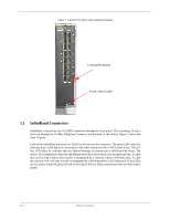
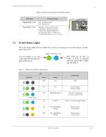
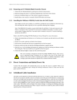
7 Figure 1: Switch Front Panel and Locking Mechanism Locking Mechanism Switch Status Lights 1.1 InfiniBand Connectors InfiniBand connectivity has 16 QSFP connectors through the front panel. The remaining 16 interfaces are through the AirMax Midplane Connector out the back of the switch. Figure 1 shows the front 16 ports. Each of the InfiniBand ports has two LEDs located next to the connector. The green LED, when lit, indicates that a valid physical connection to the other system (switch or HCA port) exists. The yellow LED when lit, indicates that the Subnet Manager is running and a valid data link exists. The yellow LED illuminates when the InfiniBand network is discovered over the physical link. A valid data activity link without data transfer is designated by a constant yellow LED indication. A valid data activity link with data transfer is designated by a blinking yellow LED indication. If the LEDs are not active, either the physical link or the logical link (or both) connections have not been established. Rev 1.1 Mellanox Technologies
-
 1
1 -
 2
2 -
 3
3 -
 4
4 -
 5
5 -
 6
6 -
 7
7 -
 8
8 -
 9
9 -
 10
10 -
 11
11 -
 12
12 -
13
-
14
-
15
-
16
-
17
-
18
-
19
-
20
-
21
-
22
-
23
-
24
-
25
-
26
 |
 |
