Dell PowerEdge M520 Rack Installation Guide - Page 25
Securing the Cables to the Strain-Relief Bar, to the system. For example
 |
View all Dell PowerEdge M520 manuals
Add to My Manuals
Save this manual to your list of manuals |
Page 25 highlights
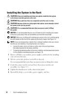
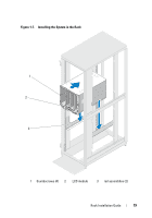
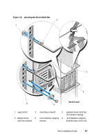
4 Locate the three notches on each segment of the enumerator. Each enumerator has the capacity to accommodate a sequence of eight cables in one of three graduated thicknesses of cable fabric. For example, large data cables seat in the largest notch in the segment and small fiber optic cables seat in the smallest notch in the segment (see Figure 1-9). 5 Identify the cable notch size on the enumerator and seat each cable in the group. Arrange the cables in the same sequence that they connect to the system. (For example, if you have a column of eight cables, seat the topmost cable in the first segment, and so on.) (See Figure 1-9.) NOTE: Depending on your cabling configuration, you can group and order the cables in a variety of ways as long as you have no more than eight cables grouped and attached to each enumerator. Figure 1-9 shows 16 cables grouped and ordered with two enumerators: one with the upper eight cables from both columns and the other with the lower eight cables from both columns. For this same example, you can also group and order each column of eight cables (not shown). Securing the Cables to the Strain-Relief Bar 1 Locate the Velcro tie wraps that are included with your system (see Figure 1-1 and Figure 1-2). 2 Facing the back of the system, position the tie wrap over the cable bundle as it connects with the strain-relief bar (see Figure 1-9). NOTE: Depending on your system configuration, there are a number of ways to wrap the cables and secure the cable bundles to the strain-relief bar using the Velcro tie wraps. 3 To secure the cables to the bar, wrap the cable bundle by passing the tie wrap around the back of the bar, and then wrapping around the cable bundle again, crossing the tie wrap in front of the cables (see Figure 1-9). 4 The cables should be wrapped securely enough to stay bundled while still able to slide on the strain-relief bar. This step ensures that you can easily move bundles of cable clear of I/O modules during removal and installation. NOTE: Ensure that you secure all power cables routed from either side of your system to the strain-relief bar with Velcro tie wraps as shown in Figure 1-9. See the Getting Started Guide for instructions on attaching the power cable retention clip, which adds additional strain relief to your system. Rack Installation Guide 23
-
 1
1 -
2
-
3
-
4
-
5
-
6
-
7
-
8
-
9
-
10
-
11
-
12
-
13
-
14
-
15
-
16
-
17
-
18
-
19
-
 20
20 -
 21
21 -
 22
22 -
 23
23 -
 24
24 -
 25
25 -
 26
26 -
 27
27 -
 28
28 -
 29
29 -
 30
30 -
31
-
32
-
33
-
34
-
35
-
36
-
37
-
38
-
39
-
40
-
41
-
42
-
43
-
44
-
45
-
46
-
47
-
48
-
49
-
50
-
51
-
52
-
53
-
54
-
55
-
56
-
57
-
58
-
59
-
60
-
61
-
62
-
63
-
64
-
65
-
66
-
67
-
68
-
69
-
70
-
71
-
72
-
73
-
74
-
75
-
76
-
77
-
78
-
79
-
80
-
81
-
82
-
83
-
84
-
85
-
86
-
87
-
88
-
89
-
90
-
91
-
92
-
93
-
94
-
95
-
96
-
97
-
98
-
99
-
100
-
101
-
102
-
103
-
104
-
105
-
106
-
107
-
108
-
109
-
110
-
111
-
112
-
113
-
114
-
115
-
116
-
117
-
118
-
119
-
120
-
121
-
122
-
123
-
124
-
125
-
126
-
127
-
128
-
129
-
130
-
131
-
132
-
133
-
134
-
135
-
136
-
137
-
138
-
139
-
140
-
141
-
142
-
143
-
144
 |
 |