Dell PowerEdge M520 Dell FC8PT Pass-Through Module Quick Start Guide and User - Page 7
View Status LEDs
 |
View all Dell PowerEdge M520 manuals
Add to My Manuals
Save this manual to your list of manuals |
Page 7 highlights
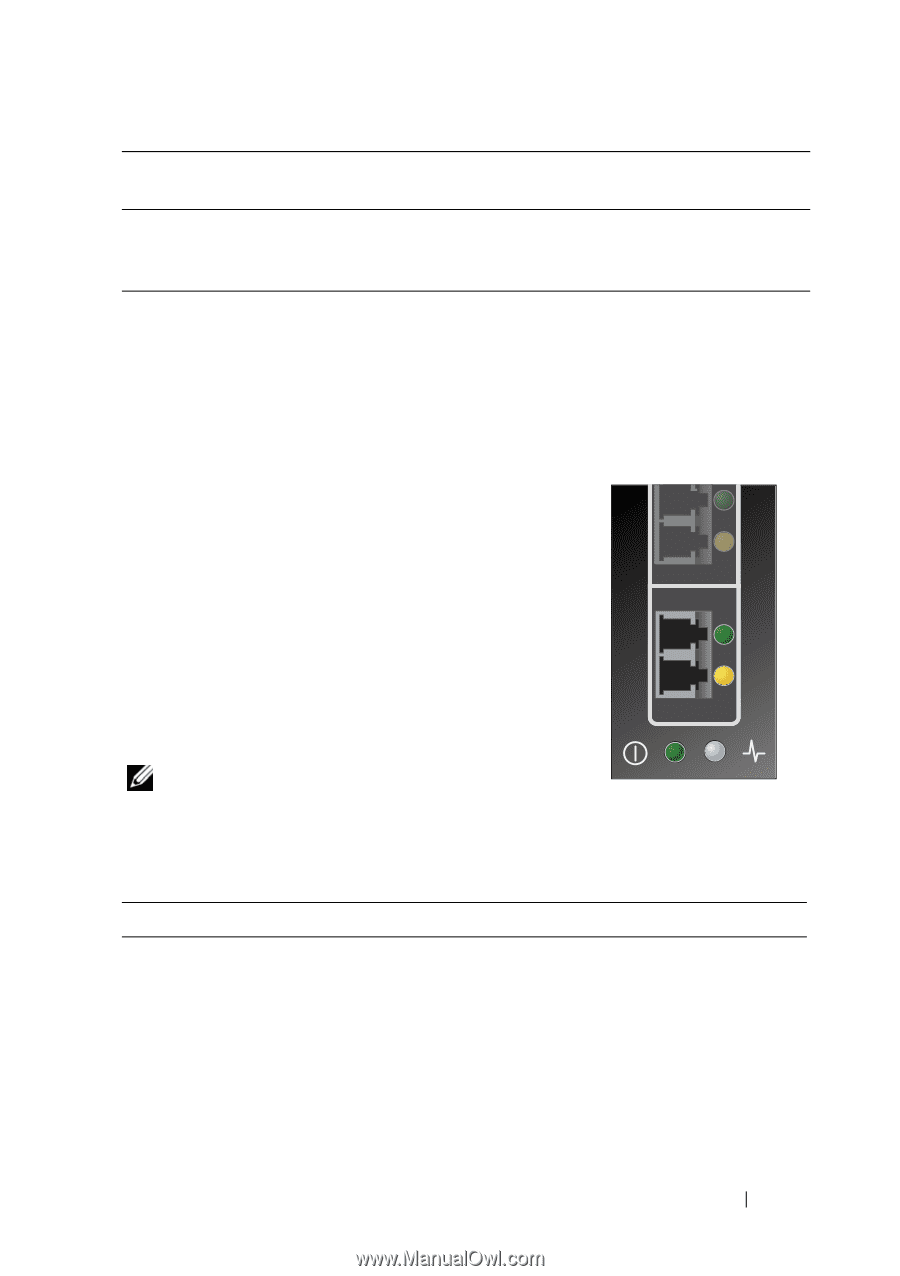
Fiber Optic Cable 50/125 μm (multimode) 500 MHz*km bandwidth cable Maximum Length Minimum Length 300 meters at 2.125 Gb/s .5 meters 150 meters at 4.25 Gb/s 50 meters at 8.5 Gb/S Connector LC 1 Connect the fiber optic cables to the LC connectors on the pass-through module. 2 Connect the other end of the cable to the target Fibre Channel device. 3. View Status LEDs The pass-through module contains several lightemitting diodes (LEDs). Each port includes a pair of LEDs (one green and one yellow) that indicate the status of the ports on the SFP. Power-on self test (POST) conditions and results are summarized in Tables 1-1 and 1-2. In addition, at the bottom of the pass-through module faceplate is an additional pair of LEDs (one blue and one green) that provide the status of the pass-through module. Pass-through module status LEDs are shown in Table 1-3, PassThrough Module Status LEDs. NOTE: For the link rate conditions, there is a one second pause when the LED is off between each group of fast blinks (2, 3, or 4). You should observe the LED sequence for several seconds to ensure that the pause is correctly identified. Table 1-1. Port Status LED - Emulex Yellow LED Off On Slow blink Fast blink Flashing Off Green LED Off Off Off Off Off On State Wake-up failure (dead board) POST failure (dead board) Wake-up failure monitor POST failure POST processing in progress Failure while functioning FC8PT Pass-Through Module 7
-
 1
1 -
 2
2 -
 3
3 -
 4
4 -
 5
5 -
 6
6 -
 7
7 -
 8
8 -
 9
9 -
 10
10 -
 11
11 -
 12
12 -
13
-
14
-
15
-
16
-
17
-
18
-
19
-
20
-
21
-
22
-
23
-
24
-
25
-
26
-
27
-
28
-
29
-
30
-
31
-
32
-
33
-
34
-
35
-
36
-
37
-
38
-
39
-
40
-
41
-
42
-
43
-
44
-
45
-
46
-
47
-
48
-
49
-
50
-
51
-
52
-
53
-
54
-
55
-
56
-
57
-
58
-
59
-
60
-
61
-
62
-
63
-
64
-
65
-
66
-
67
-
68
-
69
-
70
-
71
-
72
-
73
-
74
-
75
-
76
-
77
-
78
-
79
-
80
-
81
-
82
-
83
-
84
-
85
-
86
-
87
-
88
-
89
-
90
-
91
-
92
-
93
-
94
-
95
-
96
-
97
-
98
-
99
-
100
-
101
-
102
-
103
-
104
-
105
-
106
-
107
-
108
-
109
-
110
-
111
-
112
-
113
-
114
-
115
-
116
 |
 |