Cabling the Dell™ PowerEdge™ R710
Page 1
Table of Contents
Introduction
...............................................................................................................................................................
2
Cabling a PowerEdge R710 with CMA
.......................................................................................................................
2
2.1 Installing the Cables to the System
.................................................................................................................
2
Figure 1: System with Cables Installed
..........................................................................................................
2
2.2 Route the Power Cables Through the Strain Reliefs
.......................................................................................
3
Figure 2: Routing Power Cables Through the Strain Reliefs
.........................................................................
3
2.3 Routing the Cables Through the CMA
.............................................................................................................
3
Figure 3: Routing the Cables Through the CMA
...........................................................................................
4
Figure 4: Completed Left Side Mounted CMA Installation
............................................................................
5
Figure 5: Completed Right Side Mounted CMA Installation
..........................................................................
5
Cabling a PowerEdge R710 Without a CMA
..............................................................................................................
5
3.1 Routing the Cables
..........................................................................................................................................
5
Figure 6: Cable Routing Without a CMA
........................................................................................................
6
Replacing a Power Supply on a PowerEdge R710 with CMA
.....................................................................................
6
Figure 7: Replacing Outer Power Supply
.......................................................................................................
7
Cabling a PowerEdge R710 Installed in Static Rails
...................................................................................................
7
Figure 8: Cabling a System Installed in Static Rails
........................................................................................
7
 1
1 2
2 3
3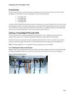 4
4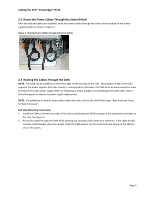 5
5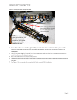 6
6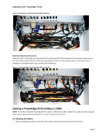 7
7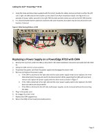 8
8 9
9

