Cable Routing Pr
ocedures for Dell™ PowerEdge™ T6
10 Systems
Page 1
Contents
Introduction
...............................................................................................................................................................
2
Section 1: Cabling a Dell™ PowerEdge™ T610 With a Cable Management Arm (CMA)
............................................
2
1.1
Connecting the CMA Cables to the System
..................................................................................................
2
1.2
Routing the Power Cables Through the Strain Reliefs
.................................................................................
3
1.3
Installation of the CMA
................................................................................................................................
3
Section 2: Cabling a Dell™ PowerEdge™ T610 System Without a CMA
.....................................................................
5
2.1
Routing the Cables
.......................................................................................................................................
5
Section 3: Replacing a Power Supply on a PowerEdge™ T610 System With a
CMA
..................................................
6
Table of Figures
Figure 1: System with Cables Installed
..................................................................................................................
2
Figure 2: Routing Power Cables Through the Strain Reliefs
.............................................................................
3
Figure 3: Routing the Cables Through the CMA
.................................................................................................
4
Figure 4: Right-Side Mounted CMA Installation
..................................................................................................
4
Figure 5: Left-Side Mounted CMA Installation
.....................................................................................................
5
Figure 6: Cable Routing Without a CMA
...............................................................................................................
5
Figure 7: Replacing the Power Supply
...................................................................................................................
6
 1
1 2
2 3
3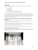 4
4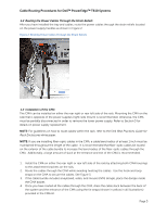 5
5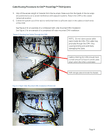 6
6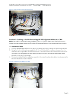 7
7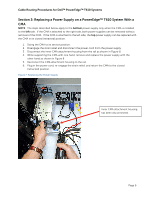 8
8

