Dell PowerEdge PDU Metered LCD Cabling PowerEdge T610 - Page 5
ocedures for Dell™ PowerEdge™ T6
 |
View all Dell PowerEdge PDU Metered LCD manuals
Add to My Manuals
Save this manual to your list of manuals |
Page 5 highlights
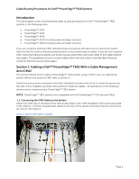
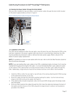
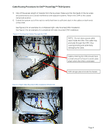
Cable Routing Procedures for Dell™ PowerEdge™ T610 Systems 1.2 Routing the Power Cables Through the Strain Reliefs After you have installed the tray and cables, route the power cables through the strain reliefs located on the power supply handles as shown in Figure 2. Figure 2: Routing Power Cables Through the Strain Reliefs 1.3 Installation of the CMA The CMA can be installed on either the rear right or rear left side of the rails. Mounting the CMA on the side that is opposite of the power supplies (right-side mount) is recommended; otherwise, the CMA must be partially disconnected in order to remove the lower power supply. Refer to Section 3 for details on power supply replacement. NOTE: For guidelines on how to route cables within the rack, refer to the Dell Best Practices Guide for Rack Enclosures white paper. NOTE: If you are installing fiber-optic cables in the CMA, a cable bend radius of at least 1 inch must be maintained throughout the length of the cable. It is recommended that fiber-optic cables be routed on the exterior of the cable bundle to increase the bend radius of the fiber-optic cables through the CMA. Additionally, a large amount of slack at the entrance and exit of the CMA is recommended. 1. Install the CMA on either the rear right or rear left side of the rails by attaching both CMA housings to the attachment brackets on the rails. 2. Route the cables through the CMA while avoiding twisting the cables. Use the hook and loop straps on the CMA to secure the cables. See Figure 3. 3. If the cable bundle includes a keyboard, video, and mouse (KVM) dongle, place the dongle inside the CMA basket. 4. Once you have routed all the cables through the CMA, dress the cable slack between the back of the system and the entrance of the CMA using the tie wraps (shown in yellow in all illustrations) provided in the CMA kit. Page 3
-
 1
1 -
 2
2 -
 3
3 -
 4
4 -
 5
5 -
 6
6 -
 7
7 -
 8
8
 |
 |
