Dell PowerEdge PDU Metered LCD Cabling PowerEdge T610 - Page 8
Replacing a Power Supply on a PowerEdge™
 |
View all Dell PowerEdge PDU Metered LCD manuals
Add to My Manuals
Save this manual to your list of manuals |
Page 8 highlights
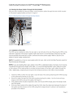
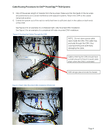
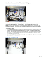
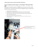
Cable Routing Procedures for Dell™ PowerEdge™ T610 Systems Section 3: Replacing a Power Supply on a PowerEdge™ T610 System With a CMA NOTE: The steps described below apply to the bottom power supply only when the CMA is installed to the left side. If the CMA is attached to the right side, both power supplies can be removed without removal of the CMA. If the CMA is attached to the left side, the top power supply can be replaced with the CMA in its closed (retracted) position. 1. Swing the CMA to its service position. 2. Disengage the strain relief and disconnect the power cord from the power supply. 3. Disconnect the inner CMA attachment housing from the rail as shown in Figure 8. 4. While supporting the CMA with one hand, remove and replace the power supply with the other hand as shown in Figure 8. 5. Reconnect the CMA attachment housing to the rail. 6. Plug in the power cord, re-engage the strain relief, and return the CMA to the closed (retracted) position. Figure 7: Replacing the Power Supply Inner CMA attachment housing has been disconnected. Page 6
-
 1
1 -
2
-
 3
3 -
 4
4 -
 5
5 -
 6
6 -
 7
7 -
 8
8
 |
 |
