Dell PowerEdge R420 Cable Routing Procedures - Page 11
Cabling a PowerEdge R320 or R420 system installed, on static rails - server
 |
View all Dell PowerEdge R420 manuals
Add to My Manuals
Save this manual to your list of manuals |
Page 11 highlights
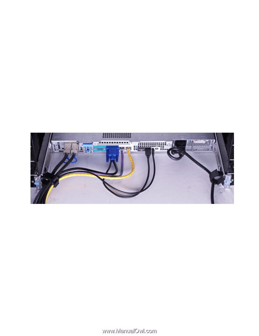
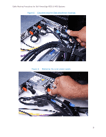
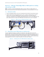
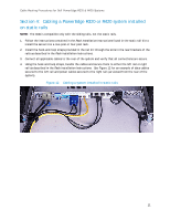
Cable Routing Procedures for Dell PowerEdge R320 & R420 Systems Section 4: Cabling a PowerEdge R320 or R420 system installed on static rails NOTE: The CMA is compatible only with the sliding rails, not the static rails. 1. Follow the instructions contained in the Rack Installation Instructions found in the static rail kit to install the server into a two-post or four-post rack. 2. Install the hook-and-loop straps provided in the rail kit through the slots in the rear brackets of the rails as described in the Rack Installation Instructions. 3. Connect all applicable cables to the rear of the system and verify that all connections are secure. 4. Using the hook-and-loop straps, bundle the cables and secure them to either the left rail or right rail as described in the Rack Installation Instructions. See Figure 12 for an example of data cables secured to the left rail and power cables secured to the right rail (as viewed from the rear of the system). Figure 12. Cabling a system installed in static rails 11
-
 1
1 -
2
-
3
-
4
-
5
-
 6
6 -
 7
7 -
 8
8 -
 9
9 -
 10
10 -
 11
11
 |
 |