Dell PowerEdge R420 Cable Routing Procedures - Page 4
Introduction, Cabling a PowerEdge R320 or R420 system with a CMA - rack server
 |
View all Dell PowerEdge R420 manuals
Add to My Manuals
Save this manual to your list of manuals |
Page 4 highlights
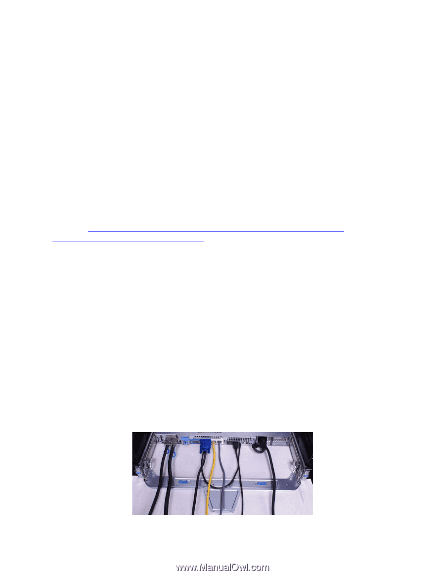
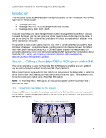
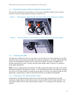
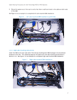
Cable Routing Procedures for Dell PowerEdge R320 & R420 Systems Introduction This white paper covers recommended cable routing procedures for the Dell™ PowerEdge™ R320 & R420 systems in the following racks: • PowerEdge 2410, 4210 • PowerEdge 2420, 4220, 4820 (including wide and deep versions) • PowerEdge Energy Smart 4020S, 4620S If you are using the optional cable management arm (CMA), following these procedures will allow you to extend the system from the rack for service without powering down or disconnecting the cables. If you are not using the CMA, following these procedures will ensure secure attachment and strain relief of the cables behind the system. For guidelines on how to route cables within the rack, refer to the Dell Best Practices Guide for Rack Enclosure white paper. For additional details regarding potential interferences between the CMA and rear-mount power distribution units (PDUs) in Dell racks as well as general information about third party rack compatibility, refer to the Dell Enterprise Systems Rail Sizing and Rack Compatibility Matrix located at http://content.dell.com/us/en/enterprise/d/business~solutions~engineeringdocs~en/Documents~rail-rack-matrix.pdf.aspx. Section 1: Cabling a PowerEdge R320 or R420 system with a CMA This section details how to cable the PowerEdge R320 & R420 systems on sliding rails using a CMA. If you are cabling the system without the optional CMA, refer to Section 3. Follow the instructions contained in the Rack Installation Instructions in the sliding rail kit to install the server into the rack. Once installed, use these instructions to install the cables. All illustrations in the following sections were created using a PowerEdge R320 system. NOTE: The PowerEdge R320 & R420 systems are backward compatible with the PowerEdge R310 & R410 rails and CMA. 1.1. Connecting the cables to the system Attach the CMA tray to the back of the rails as described in the CMA Installation Instructions provided in the CMA kit. Connect all applicable cables to the rear of the system and verify that all connections are secure. See Figure 1. Figure 1. System with cables installed 4
-
 1
1 -
 2
2 -
 3
3 -
 4
4 -
 5
5 -
 6
6 -
 7
7 -
 8
8 -
 9
9 -
 10
10 -
11
 |
 |