Dell PowerEdge R905 Installation and Troubleshooting Guide (.htm)
Dell PowerEdge R905 Manual
 |
View all Dell PowerEdge R905 manuals
Add to My Manuals
Save this manual to your list of manuals |
Dell PowerEdge R905 manual content summary:
- Dell PowerEdge R905 | Installation and Troubleshooting Guide (.htm) - Page 1
Dell™ Rack Installation Guide Guide d'installation du rack Dell™ Dell™ Rack-Installationshandbuch Dell Guía de instalación del rack Dell™ - Dell PowerEdge R905 | Installation and Troubleshooting Guide (.htm) - Page 2
- Dell PowerEdge R905 | Installation and Troubleshooting Guide (.htm) - Page 3
Dell™ Rack Installation Guide - Dell PowerEdge R905 | Installation and Troubleshooting Guide (.htm) - Page 4
to hardware or loss of data and tells you how to avoid the problem. CAUTION: A CAUTION indicates a potential for property damage, personal injury, or entities claiming the marks and names or their products. Dell Inc. disclaims any proprietary interest in trademarks and trade names other than its - Dell PowerEdge R905 | Installation and Troubleshooting Guide (.htm) - Page 5
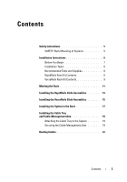
Contents Safety Instructions 5 SAFETY: Rack Mounting of Systems 5 Installation Instructions 6 Before You Begin 7 Installation Tasks 8 Recommended Tools and Supplies 8 RapidRails Rack Kit Contents 8 VersaRails Rack Kit Contents 9 Marking the Rack 11 Installing the RapidRails Slide Assemblies - Dell PowerEdge R905 | Installation and Troubleshooting Guide (.htm) - Page 6
4 Contents - Dell PowerEdge R905 | Installation and Troubleshooting Guide (.htm) - Page 7
are intended to be installed in an approved rack by trained service technicians. If you install the kit in any other rack, be sure that the rack meets the specifications. • Before working on the rack, make sure that the stabilizers are secured to the rack, extended to the floor, and that the full - Dell PowerEdge R905 | Installation and Troubleshooting Guide (.htm) - Page 8
that proper airflow is provided to components in the rack. • Do not step on or stand on any system/component when servicing other systems/components in a rack. Installation Instructions This installation guide provides instructions for trained service technicians installing one or more systems in an - Dell PowerEdge R905 | Installation and Troubleshooting Guide (.htm) - Page 9
feet help prevent the rack from tipping over when a system or other component is pulled out of the rack with the slide assemblies fully extended. See the documentation provided with the rack cabinet for instructions on installing and anchoring the stabilizer feet. Dell™ Rack Installation Guide 7 - Dell PowerEdge R905 | Installation and Troubleshooting Guide (.htm) - Page 10
: 1 Marking the rack (if necessary) 2 Installing the rail assemblies in the rack: • RapidRails installation • VersaRails installation 3 Installing the system in the rack 4 Installing the cable tray and cable-management arm 5 Routing cables Recommended Tools and Supplies • A #2 Phillips screwdriver - Dell PowerEdge R905 | Installation and Troubleshooting Guide (.htm) - Page 11
VersaRails Rack Kit Contents The VersaRails rack kit includes the following items (see Figure 1-2): • One pair of VersaRails slide assemblies • One cable-management arm • One cable-management arm retainer • One cable tray • One status indicator cable (if applicable) Dell™ Rack Installation Guide 9 - Dell PowerEdge R905 | Installation and Troubleshooting Guide (.htm) - Page 12
screw. Figure 1-2. VersaRails Rack Kit Contents 1 2 3 4 5 6 7 1 cable-management arm 2 Velcro strap 3 cable tray 4 cable management arm retainer 5 status indicator cable (if applicable) 6 VersaRails slide assemblies 7 Ten 32 x 0.5 flange-head Phillips screws 10 Dell™ Rack Installation Guide - Dell PowerEdge R905 | Installation and Troubleshooting Guide (.htm) - Page 13
vertical rails where you want to locate the bottom of the system you are installing in the rack cabinet. The bottom of each 1-U space is at the middle of the narrowest metal area between holes (marked with a horizontal line on some rack cabinets- see Figure 1-4). Dell™ Rack Installation Guide 11 - Dell PowerEdge R905 | Installation and Troubleshooting Guide (.htm) - Page 14
, place a mark just above the top hole). This mark or piece of tape indicates where the system's upper edge will be located on the vertical rails (see Figure 1-4). Figure 1-4. Marking the Vertical Rails 1 1 tape on vertical rail 12 Dell™ Rack Installation Guide - Dell PowerEdge R905 | Installation and Troubleshooting Guide (.htm) - Page 15
in the square holes and the push button pops out and clicks. 4 Repeat steps 1 through 3 for the slide assembly on the other side of the rack. NOTE: Ensure that the rails are mounted at the same vertical position on both sides of the rack. Dell™ Rack Installation Guide 13 - Dell PowerEdge R905 | Installation and Troubleshooting Guide (.htm) - Page 16
Figure 1-5. Installing the RapidRails Slide Assemblies 1 2 3 5 4 1 push button 3 mounting hooks (2) 5 front of rack 2 slide-assembly mounting-bracket flange 4 slide assemblies (2) 14 Dell™ Rack Installation Guide - Dell PowerEdge R905 | Installation and Troubleshooting Guide (.htm) - Page 17
flange holes will be used later for installing the cable-management arm retainer. 5 Repeat steps 1 through 4 for the slide assembly on the other side of the rack. NOTE: Ensure that the rails are mounted at the same vertical position on both sides of the rack. Dell™ Rack Installation Guide 15 - Dell PowerEdge R905 | Installation and Troubleshooting Guide (.htm) - Page 18
Figure 1-6. Installing the VersaRails Rail Assemblies 1 3 4 2 1 slide-assembly mounting-bracket flange 3 flange-head Phillips screws (2) 2 slide assemblies (2) 4 front of rack 16 Dell™ Rack Installation Guide - Dell PowerEdge R905 | Installation and Troubleshooting Guide (.htm) - Page 19
of the system. 3 Tilt the front of the system upward while aligning the back shoulder screws on the sides of the system with the back slots on the slide assemblies (see Figure 1-7). Dell™ Rack Installation Guide 17 - Dell PowerEdge R905 | Installation and Troubleshooting Guide (.htm) - Page 20
mechanism clicks into place, locking the slide to the system (see Figure 1-7). 6 Pull up on the slide-release latches and push the system into the rack. 7 Tighten the thumbscrews on the rack front panel. 18 Dell™ Rack Installation Guide - Dell PowerEdge R905 | Installation and Troubleshooting Guide (.htm) - Page 21
the tab on the front end of the cable-management arm into the latch on the cable tray until the latch clicks (see Figure 1-8). 2 Push the tab on the unattached end of the cable-management arm into the latch on the end of the slide assembly until the latch clicks. Dell™ Rack Installation Guide 19 - Dell PowerEdge R905 | Installation and Troubleshooting Guide (.htm) - Page 22
management arm 5 captive thumbscrews (4) 7 Velcro strap 9 mounting tabs (2) 2 tabs 4 cable-management retainer 6 captive thumbscrews (2) 8 formed metal tabs NOTE: Figure 1-8 illustrates both rack rail types that demonstrate how to connect the rack to your system. 20 Dell™ Rack Installation Guide - Dell PowerEdge R905 | Installation and Troubleshooting Guide (.htm) - Page 23
within the arms. 3 Route the system status-indicator cable along the cable-management arm through the upper basket, and then, if desired, through the lower basket. Insert the LED end into one of the indicator slots on the cablemanagement arm (see Figure 1-9). Dell™ Rack Installation Guide 21 - Dell PowerEdge R905 | Installation and Troubleshooting Guide (.htm) - Page 24
the system back panel. For details on cable connections, see your system's Installation and Troubleshooting Guide and the User's Guide. NOTE: Use the strain-relief loops (if available) on the back of the power supplies to provide strain relief for the power cables. 22 Dell™ Rack Installation Guide - Dell PowerEdge R905 | Installation and Troubleshooting Guide (.htm) - Page 25
the cables with the vertical Velcro strap (see Figure 1-10). 6 Route the cables along the cable-management arm through both cable baskets, starting with the upper basket and exiting the lower basket (see Figure the front of the system to the front vertical rail. Dell™ Rack Installation Guide 23 - Dell PowerEdge R905 | Installation and Troubleshooting Guide (.htm) - Page 26
Figure 1-10. Routing Cables on the Cable-Management Arm 1 2 1 cable tray Velcro strap (6) 2 CMA Velcro strap 24 Dell™ Rack Installation Guide - Dell PowerEdge R905 | Installation and Troubleshooting Guide (.htm) - Page 27
of the rack to verify that the cables are routed correctly and do not bind, stretch, or pinch with the movement of the cable-management arm. Adjust and then slide the system into the rack. 12 Secure the cable-management arm retainer to the back of the rack using the captive thumbscrews. NOTE: Be - Dell PowerEdge R905 | Installation and Troubleshooting Guide (.htm) - Page 28
26 Dell™ Rack Installation Guide - Dell PowerEdge R905 | Installation and Troubleshooting Guide (.htm) - Page 29
Guide d'installation du rack Dell™ - Dell PowerEdge R905 | Installation and Troubleshooting Guide (.htm) - Page 30
de marques peuvent être utilisés dans ce document pour faire référence aux entités se réclamant de ces marques et de ces noms ou à leurs produits. Dell Inc. dénie tout intérêt propriétaire vis-à-vis des marques et des noms de marque autres que les siens. Novembre 2007 N/P TR669 Rév. A00 - Dell PowerEdge R905 | Installation and Troubleshooting Guide (.htm) - Page 31
sécurit 31 SÉCURITÉ : montage en rack des systèmes . . . . 31 Instructions d'installation 33 Avant de commencer 33 Tâches d'installation 34 Outils et fournitures recommandés 35 Contenu du kit RapidRails 35 Contenu du kit VersaRails 37 Marquage du rack 39 Installation des assemblages à glissi - Dell PowerEdge R905 | Installation and Troubleshooting Guide (.htm) - Page 32
30 Table des matières - Dell PowerEdge R905 | Installation and Troubleshooting Guide (.htm) - Page 33
entière responsabilité de faire évaluer par un organisme de sécurité agréé la combinaison finale formée par le système, le kit d'installation et l'armoire rack. Le constructeur décline toute responsabilité et garantie liée à ces combinaisons. Guide d'installation du rack Dell™ 31 - Dell PowerEdge R905 | Installation and Troubleshooting Guide (.htm) - Page 34
doit pas dépasser 80 % de la capacité du circuit. • Assurez-vous que les éléments installés dans le rack disposent d'une ventilation suffisante. • Ne montez jamais sur un système ou composant lorsque vous intervenez sur d'autres systèmes ou composants du rack. 32 Guide d'installation du rack Dell™ - Dell PowerEdge R905 | Installation and Troubleshooting Guide (.htm) - Page 35
guide d'installation s'adresse à des techniciens de maintenance qualifiés. Il contient les instructions relatives à l'installation d'un ou de plusieurs systèmes dans un rack à châssis ouvert ou une armoire rack. Le kit de rack RapidRails™ peut être installé sans outils dans toutes les armoires racks - Dell PowerEdge R905 | Installation and Troubleshooting Guide (.htm) - Page 36
) 2 Installation des assemblages de rails dans le rack • Installation du kit RapidRails • Installation du kit VersaRails 3 Installation du système dans le rack 4 Installation du chemin de câbles et du bras de gestion des câbles 5 Acheminement des câbles 34 Guide d'installation du rack Dell™ - Dell PowerEdge R905 | Installation and Troubleshooting Guide (.htm) - Page 37
• Une tige de retenue pour le bras de gestion des câbles • Un chemin de câbles • Un câble de voyant d'état (si nécessaire) • Une bande Velcro Guide d'installation du rack Dell™ 35 - Dell PowerEdge R905 | Installation and Troubleshooting Guide (.htm) - Page 38
Figure 1-1. Contenu du kit RapidRails 2 1 3 4 5 6 1 Bras de gestion des câbles 3 Chemin de câbles 5 Câble de voyant d'état (si nécessaire) 2 Bande Velcro 4 Tige de retenue 6 Assemblages à glissière RapidRails 36 Guide d'installation du rack Dell™ - Dell PowerEdge R905 | Installation and Troubleshooting Guide (.htm) - Page 39
nécessaire) • Huit vis cruciformes à tête plate 10-32 x 0,5 pouce • Une bande Velcro REMARQUE : Les vis non métriques décrites dans les illustrations et les instructions sont identifiées en fonction de leur taille et de leur nombre de filets par pouce. Par exemple, une vis cruciforme n° 10 avec 32 - Dell PowerEdge R905 | Installation and Troubleshooting Guide (.htm) - Page 40
Velcro 3 Chemin de câbles 4 Tige de retenue 5 Câble de voyant d'état (si nécessaire) 6 Assemblages à glissière VersaRails 7 Dix vis cruciformes à tête plate 32 x 0,5 pouce 38 Guide d'installation du rack Dell™ - Dell PowerEdge R905 | Installation and Troubleshooting Guide (.htm) - Page 41
souhaitez placer le bas du système à installer dans l'armoire rack. Le bas de chaque espace de 1 U se trouve au milieu de la zone métallique la plus étroite entre les trous (repérée par une ligne horizontale sur certaines armoires racks ; voir Figure 1-4). Guide d'installation du rack Dell™ 39 - Dell PowerEdge R905 | Installation and Troubleshooting Guide (.htm) - Page 42
-dessus du trou supérieur. Cette marque ou ce morceau de bande adhésive indique la position future du haut du système sur les rails verticaux (voir Figure 1-4). Figure 1-4. Marquage des rails verticaux 1 1 Bande apposée sur le rail vertical 40 Guide d'installation du rack Dell™ - Dell PowerEdge R905 | Installation and Troubleshooting Guide (.htm) - Page 43
support de montage s'insère à l'endroit approprié sur le rack (voir Figure 1-5). Le crochet de fixation supérieur situé sur la collerette avant du support côté du rack. REMARQUE : Vérifiez que les rails sont montés à la même hauteur des deux côtés du rack. Guide d'installation du rack Dell™ 41 - Dell PowerEdge R905 | Installation and Troubleshooting Guide (.htm) - Page 44
Figure 1-5. Installation des assemblages à glissière RapidRails 1 2 3 5 4 1 Bouton poussoir 3 Crochets de montage (2) 5 Avant du rack 2 Collerette du support de montage de l'assemblage à glissière 4 Assemblages à glissière (2) 42 Guide d'installation du rack Dell™ - Dell PowerEdge R905 | Installation and Troubleshooting Guide (.htm) - Page 45
rack (voir Figure 1-6). Les trous situés à l'avant du support de montage doivent s'aligner avec ceux qui se trouvent entre les marques faites sur le rail côté du rack. REMARQUE : Vérifiez que les rails sont montés à la même hauteur des deux côtés du rack. Guide d'installation du rack Dell™ 43 - Dell PowerEdge R905 | Installation and Troubleshooting Guide (.htm) - Page 46
Figure 1-6. Installation des assemblages à glissière VersaRails 1 3 4 2 1 Collerette du support de montage de l'assemblage à glissière 3 Vis cruciformes à tête plate (2) 2 Assemblages à glissière (2) 4 Avant du rack 44 Guide d'installation du rack Dell™ - Dell PowerEdge R905 | Installation and Troubleshooting Guide (.htm) - Page 47
faisant correspondre les vis à épaulement arrière, sur les côtés du système, avec les fentes situées à l'arrière des assemblages à glissière (voir Figure 1-7). Guide d'installation du rack Dell™ 45 - Dell PowerEdge R905 | Installation and Troubleshooting Guide (.htm) - Page 48
Figure 1-7. Installation du système dans le rack 1 1 Mécanisme de verrouillage du système 4 Engagez la vis à épaulement arrière les loquets de dégagement vers le haut et poussez le système dans le rack. 7 Serrez les vis moletées sur le panneau avant du rack. 46 Guide d'installation du rack Dell™ - Dell PowerEdge R905 | Installation and Troubleshooting Guide (.htm) - Page 49
à l'arrière du système varie en fonction du modèle qui vous a été fourni avec le kit de rails. Les deux chemins de câbles sont représentés Figure 1-8. Montage du type I 1 Alignez les pattes métalliques au système à l'aide des deux vis moletées imperdables. Guide d'installation du rack Dell™ 47 - Dell PowerEdge R905 | Installation and Troubleshooting Guide (.htm) - Page 50
l'aide des deux vis moletées imperdables. PRÉCAUTION : Le chemin de câbles n'est pas conçu pour supporter le poids du système. Ne l'utilisez pas pour soulever ce dernier. Pour soulever le système, saisissez glissière, jusqu'à ce que vous sentiez un déclic. 48 Guide d'installation du rack Dell™ - Dell PowerEdge R905 | Installation and Troubleshooting Guide (.htm) - Page 51
bras de gestion des câbles 3 2 1 Arrière du système 4 Arrière du rack 5 6 Montage du type I 7 8 9 Montage du type II 1 Loquet du chemin de métalliques REMARQUE : La figure 1-8 présente les deux types de rails permettant de connecter le rack au système. Guide d'installation du rack Dell™ 49 - Dell PowerEdge R905 | Installation and Troubleshooting Guide (.htm) - Page 52
conduit inférieur. Insérez l'extrémité dotée du voyant dans l'un des emplacements appropriés, sur le bras de gestion des câbles (voir Figure 1-9). 50 Guide d'installation du rack Dell™ - Dell PowerEdge R905 | Installation and Troubleshooting Guide (.htm) - Page 53
ème 3 Loquet de dégagement 5 Connecteur du voyant d'état du système 4 5 2 Boucles (une par bloc d'alimentation, le cas échéant) 4 Voyant d'état du système Guide d'installation du rack Dell™ 51 - Dell PowerEdge R905 | Installation and Troubleshooting Guide (.htm) - Page 54
des câbles, reportez-vous aux documents Installation and Troubleshooting Guide (Guide d'installation et de dépannage) et User's Guide (Guide d'utilisation) fournis avec le système. REMARQUE les vis moletées fixant l'avant du système au rail vertical avant. 52 Guide d'installation du rack Dell™ - Dell PowerEdge R905 | Installation and Troubleshooting Guide (.htm) - Page 55
Figure 1-10. Acheminement des câbles dans le bras de gestion des câbles 1 2 1 Bande Velcro du chemin de câbles (6) 2 Bande Velcro du bras de gestion des câbles Guide d'installation du rack Dell™ 53 - Dell PowerEdge R905 | Installation and Troubleshooting Guide (.htm) - Page 56
dans le rack puis ressortez- cessaire. REMARQUE : Si vous tirez le système complètement hors du rack, les assemblages à glissière se verrouillent dans cette position. Pour les le système dans le rack. 12 Fixez la tige de retenue du bras de gestion des câbles sur l'arrière du rack, à l'aide des vis - Dell PowerEdge R905 | Installation and Troubleshooting Guide (.htm) - Page 57
Dell™ RackInstallationshandbuch - Dell PowerEdge R905 | Installation and Troubleshooting Guide (.htm) - Page 58
Hardware oder Verlust von Daten an und zeigt Ihnen, wie man das Problem vermeidet. VORSICHT: Hiermit werden Sie auf eine potentiell gefährliche Situation und Handelsbezeichnungen sind Eigentum der entsprechenden Hersteller und Firmen. Dell Inc. verzichtet auf alle Besitzrechte an Marken und - Dell PowerEdge R905 | Installation and Troubleshooting Guide (.htm) - Page 59
61 Vorbereitungen 61 Ablauf der Installation 63 Empfohlene Werkzeuge und Zubehör 63 Inhalt des RapidRails-Rack-Kits 63 Inhalt des VersaRails-Rack-Kits 65 Markieren des Racks 67 Einbauen der RapidRails-Laufschienen 70 Einbauen der VersaRails-Laufschienen 72 Installation des Systems im - Dell PowerEdge R905 | Installation and Troubleshooting Guide (.htm) - Page 60
58 Inhalt - Dell PowerEdge R905 | Installation and Troubleshooting Guide (.htm) - Page 61
Rack einbauen, installieren Sie bei frei stehenden (einzelnen) Racks die vorderen und seitlichen Stabilisatoren und bei Racks, die mit anderen Racks Sie selbst die Eignung der endgültigen Kombination von System und Rack-Kit für einen bestimmten Gestellschrank durch eine zugelassene Prüfbehörde - Dell PowerEdge R905 | Installation and Troubleshooting Guide (.htm) - Page 62
des Stromkreises nicht überschreiten. • Stellen Sie sicher, dass eine ausreichende Luftzufuhr zu den Komponenten im Rack gewährleistet ist. • Stellen Sie sich nicht auf Systeme oder Komponenten, wenn Sie an anderen Komponenten in einem Rack Arbeiten durchführen. 60 Dell™ Rack-Installationshandbuch - Dell PowerEdge R905 | Installation and Troubleshooting Guide (.htm) - Page 63
mehrere Systeme in einem Rack installieren, schließen Sie Rack bewegen. Vermeiden Sie lange bzw. steile Neigungen oder Rampen, auf denen Sie die Kontrolle über das Rack verlieren könnten. Fahren Sie die höhenverstellbaren Füße aus, damit das Rack abgestützt wird und nicht wegrollen kann. Dell™ Rack - Dell PowerEdge R905 | Installation and Troubleshooting Guide (.htm) - Page 64
, dass das Rack umkippt, wenn ein System oder eine andere Komponente auf den Laufschienen vollständig aus dem Rack gezogen wird. Anleitungen zur Installation und Befestigung der Stabilisatoren finden Sie in der mit dem Gestellschrank gelieferten Dokumentation. 62 Dell™ Rack-Installationshandbuch - Dell PowerEdge R905 | Installation and Troubleshooting Guide (.htm) - Page 65
-Rack-Kits Das RapidRails-Rack-Kit enthält folgende Teile (siehe Abbildung 1-1): • Ein Paar RapidRails-Laufschienen • Ein Kabelführungsarm • Ein Kabelführungsarmhalter • Eine Kabelablage • Ein Statusanzeigekabel (falls zutreffend) • Ein Klettverschluss-Streifen Dell™ Rack-Installationshandbuch - Dell PowerEdge R905 | Installation and Troubleshooting Guide (.htm) - Page 66
Abbildung 1-1. Inhalt des RapidRails-Rack-Kits 2 1 3 4 5 6 1 Kabelführungsarm 3 Kabelablage 5 Statusanzeigekabel (falls zutreffend) 2 Klettstreifen 4 Kabelführungsarmhalter 6 VersaRails-Laufschienen 64 Dell™ Rack-Installationshandbuch - Dell PowerEdge R905 | Installation and Troubleshooting Guide (.htm) - Page 67
Inhalt des VersaRails-Rack-Kits Das VersaRails-Rack-Kit enthält folgende Teile (siehe Abbildung 1-2): • Ein Paar VersaRails-Laufschienen • Ein Kabelführungsarm • Ein B. eine Kreuzschlitzschraube Nr. 10 mit 32 Windungen pro Zoll als 10-32-Schraube bezeichnet. Dell™ Rack-Installationshandbuch 65 - Dell PowerEdge R905 | Installation and Troubleshooting Guide (.htm) - Page 68
Abbildung 1-2. Inhalt des VersaRails-Rack-Kits 1 3 5 6 2 4 7 1 Kabelführungsarm 3 Kabelablage 5 Statusanzeigekabel (falls zutreffend) 7 Zehn 32 x 0,5-Zoll KreuzschlitzBundschrauben 2 Klettstreifen 4 Kabelführungsarmhalter 6 VersaRails-Laufschienen 66 Dell™ Rack-Installationshandbuch - Dell PowerEdge R905 | Installation and Troubleshooting Guide (.htm) - Page 69
erforderlich. Abbildung 1-3. Eine Rack-Einheit 1U (44 mm) 12,7 mm 15,9 mm 15,9 mm 12,7 mm VORSICHT: Wenn Sie mehr als ein System installieren, montieren Sie die Laufschienen so, dass sich das erste System in der untersten möglichen Position im Rack befindet. Dell™ Rack-Installationshandbuch 67 - Dell PowerEdge R905 | Installation and Troubleshooting Guide (.htm) - Page 70
(7 Zoll) über Ihrer ersten Markierung eine weitere Markierung an (oder zählen Sie in einem Rack nach EIA-310-Standard zwölf Löcher nach oben). Markieren Sie die vorderen vertikalen Schienen mit des Systems an den vertikalen Schienen an (siehe Abbildung 1-4). 68 Dell™ Rack-Installationshandbuch - Dell PowerEdge R905 | Installation and Troubleshooting Guide (.htm) - Page 71
Abbildung 1-4. Markieren der vertikalen Schienen 1 1 Kreppband auf der vertikalen Schiene Dell™ Rack-Installationshandbuch 69 - Dell PowerEdge R905 | Installation and Troubleshooting Guide (.htm) - Page 72
an, dass der Montagehalterungsflansch an der korrekten Stelle am Rack anliegt (siehe Abbildung 1-5). Der obere Montagehaken am vorderen für die Schiebeeinheit auf der anderen Seite des Racks. ANMERKUNG: Achten Sie darauf, dass die Schienen auf jeder Rack-Seite in der gleichen Höhe an den vertikalen - Dell PowerEdge R905 | Installation and Troubleshooting Guide (.htm) - Page 73
Abbildung 1-5. Einbauen der RapidRails-Laufschienen 1 2 3 5 4 1 Drucktaste 3 Montagehaken (2) 5 Rack-Vorderseite 2 Montagehalterungsflansch der Schiebeeinheiten 4 Laufschienen (2) Dell™ Rack-Installationshandbuch 71 - Dell PowerEdge R905 | Installation and Troubleshooting Guide (.htm) - Page 74
die Markierung mit der richtigen Zahl) am Rack passt (siehe Abbildung 1-6). Die Löcher an Ziehen Sie den Montagehalterungsflansch auf der Rack-Rückseite nach hinten, bis seine Montagel der anderen Seite des Racks. ANMERKUNG: Achten Sie darauf, dass die Schienen auf jeder Rack-Seite in der gleichen - Dell PowerEdge R905 | Installation and Troubleshooting Guide (.htm) - Page 75
Abbildung 1-6. Einbauen der VersaRails-Gleitschienen 1 3 4 2 1 Montagehalterungsflansch der Schiebeeinheiten 3 Kreuzschlitzbundschrauben (2) 2 Laufschienen (2) 4 Rack-Vorderseite Dell™ Rack-Installationshandbuch 73 - Dell PowerEdge R905 | Installation and Troubleshooting Guide (.htm) - Page 76
Systems nach oben und bringen Sie die hinteren Ansatzschrauben auf den Seiten des Systems mit den hinteren Schlitzen der Laufschienen in Übereinstimmung (siehe Abbildung 1-7). 74 Dell™ Rack-Installationshandbuch - Dell PowerEdge R905 | Installation and Troubleshooting Guide (.htm) - Page 77
Abbildung 1-7. Installation des Systems im Rack 1 1 Systemverriegelungsmechanismus 4 Führen Sie zunächst die hinteren Ansatzschrauben in nach oben, und schieben Sie das System in das Rack. 7 Ziehen Sie die Rändelschrauben auf der Frontplatte des Racks fest. Dell™ Rack-Installationshandbuch 75 - Dell PowerEdge R905 | Installation and Troubleshooting Guide (.htm) - Page 78
drehen Sie die Kabelführung in die gesicherte Position nach unten (siehe Abbildung 1-8). 3 Befestigen Sie die Kabelführung mit den zwei Rändelschrauben am System. 76 Dell™ Rack-Installationshandbuch - Dell PowerEdge R905 | Installation and Troubleshooting Guide (.htm) - Page 79
die Lasche am vorderen Ende des Kabelführungsarms bis zum Einrasten in den Halteriegel der Kabelablage (siehe Abbildung 1-8). 2 Drücken Sie die Lasche am freien Ende des Kabelführungsarms bis zum Einrasten in den Halteriegel am anderen Ende der Schiebeeinheit. Dell™ Rack-Installationshandbuch 77 - Dell PowerEdge R905 | Installation and Troubleshooting Guide (.htm) - Page 80
Kabelführungsarm 5 Rändelschrauben (4) 7 Klettstreifen 9 Montagehalterungen (2) 2 Zungen 4 Kabelführungshalter 6 Rändelschrauben (2) 8 Metallzungen ANMERKUNG: Abbildung 1-8 zeigt die Befestigung des Racks am System für zwei unterschiedliche Kabelschienentypen. 78 Dell™ Rack-Installationshandbuch - Dell PowerEdge R905 | Installation and Troubleshooting Guide (.htm) - Page 81
Verlegen Sie das Statusanzeigekabel entlang des Kabelführungsarms durch den oberen Kabeltunnel und danach bei Bedarf durch den unteren Kabeltunnel. Befestigen Sie das LED-Ende des Kabels in einem der Anzeigesteckplätze am Kabelführungsarm (siehe Abbildung 1-9). Dell™ Rack-Installationshandbuch 79 - Dell PowerEdge R905 | Installation and Troubleshooting Guide (.htm) - Page 82
Abbildung 1-9. Installation des Statusanzeigekabels 1 2 3 4 5 1 Stecker des Systemstatusanzeigekabels 2 Zugentlastungsschlaufen (eine pro Netzteil, falls verfügbar) 3 Sperrklinke 4 Systemstatusanzeige 5 Steckplatz für Systemstatusanzeige 80 Dell™ Rack-Installationshandbuch - Dell PowerEdge R905 | Installation and Troubleshooting Guide (.htm) - Page 83
der Biegung des Kabeltunnels. 9 Schließen Sie die Kabeltunnel. 10 Lösen Sie die Rändelschrauben, mit denen die Systemvorderseite an der vorderen vertikalen Schiene gesichert wird. Dell™ Rack-Installationshandbuch 81 - Dell PowerEdge R905 | Installation and Troubleshooting Guide (.htm) - Page 84
Abbildung 1-10. Kabel am Kabelführungsarm verlegen 1 2 1 Klettstreifen für die Kabelablage (6) 2 CMA-Klettstreifen 82 Dell™ Rack-Installationshandbuch - Dell PowerEdge R905 | Installation and Troubleshooting Guide (.htm) - Page 85
11 Schieben Sie das System in das Rack hinein und ziehen Sie es wieder heraus, um zu ü Gleitschiene, und schieben Sie dann das System in das Rack. 12 Sichern Sie die Kabelführungsarmklammer mit den Rändelschrauben an der Rückseite des Racks. ANMERKUNG: Verlegen Sie die Kabel unter der Klammerstrebe, - Dell PowerEdge R905 | Installation and Troubleshooting Guide (.htm) - Page 86
84 Dell™ Rack-Installationshandbuch - Dell PowerEdge R905 | Installation and Troubleshooting Guide (.htm) - Page 87
Dell - Dell PowerEdge R905 | Installation and Troubleshooting Guide (.htm) - Page 88
2007 Dell Inc Dell Inc Dell、DELL ロゴ、RapidRails および VersaRails は Dell Inc Intel、Pentium および Celeron は Intel Corporation Microsoft および Windows Microsoft Corporation Dell Inc 2007 年 11 月 P/N TR669 Rev. A00 - Dell PowerEdge R905 | Installation and Troubleshooting Guide (.htm) - Page 89
目次 89 89 90 91 92 93 RapidRails 93 VersaRails 95 97 RapidRails 99 VersaRails 101 103 105 105 106 108 目次 87 - Dell PowerEdge R905 | Installation and Troubleshooting Guide (.htm) - Page 90
88 目次 - Dell PowerEdge R905 | Installation and Troubleshooting Guide (.htm) - Page 91
2 1 Dell 89 - Dell PowerEdge R905 | Installation and Troubleshooting Guide (.htm) - Page 92
AC 80 1 RapidRails VersaRails RapidRails VersaRails 1 1 90 Dell - Dell PowerEdge R905 | Installation and Troubleshooting Guide (.htm) - Page 93
RapidRails 注意:RapidRails ANSI EIA)規格 ANSI/EIA-310-D-92 IEC)297 DIN)41494 1 1 1 Dell 91 - Dell PowerEdge R905 | Installation and Troubleshooting Guide (.htm) - Page 94
1 2 • RapidRails • VersaRails 3 4 5 92 Dell - Dell PowerEdge R905 | Installation and Troubleshooting Guide (.htm) - Page 95
• #2 RapidRails RapidRails 1-1 • RapidRails 1 1 1 1 1 1 本 Dell 93 - Dell PowerEdge R905 | Installation and Troubleshooting Guide (.htm) - Page 96
図 1-1. RapidRails 2 1 3 4 5 6 1 2 3 4 5 6 VersaRails 94 Dell - Dell PowerEdge R905 | Installation and Troubleshooting Guide (.htm) - Page 97
VersaRails VersaRails 1-2 • VersaRails 1 1 1 1 1 10-32 x 0.5 8 1 本 1 32 10 10-32 Dell 95 - Dell PowerEdge R905 | Installation and Troubleshooting Guide (.htm) - Page 98
図 1-2. VersaRails 1 3 5 6 2 4 7 1 2 3 4 5 6 VersaRails 7 32 x 0.5 10 本 96 Dell - Dell PowerEdge R905 | Installation and Troubleshooting Guide (.htm) - Page 99
4 U(約 18 cm 1-3 図 1-3. 1 1 U) 1 U(44 mm) 12.7 mm 15.9 mm 15.9 mm 12.7 mm 1 1 各 1 U 1-4 Dell 97 - Dell PowerEdge R905 | Installation and Troubleshooting Guide (.htm) - Page 100
2 18 cm EIA-310 12 1-4 図 1-4 1 1 98 Dell - Dell PowerEdge R905 | Installation and Troubleshooting Guide (.htm) - Page 101
RapidRails 1 RapidRails 1 1-5 2 2 1-5 3 4 1 1 ~ 3 Dell 99 - Dell PowerEdge R905 | Installation and Troubleshooting Guide (.htm) - Page 102
図 1-5. RapidRails 1 2 3 5 4 1 3 2) 5 2 4 2) 100 Dell - Dell PowerEdge R905 | Installation and Troubleshooting Guide (.htm) - Page 103
VersaRails 1 VersaRails 1-6 2 10-32 x 0.5 1-6 3 4 10-32 x 0.5 2 番目と 3 5 1 1 ~ 4 Dell 101 - Dell PowerEdge R905 | Installation and Troubleshooting Guide (.htm) - Page 104
図 1-6. VersaRails 1 3 4 2 1 2 2 3 2) 4 102 Dell - Dell PowerEdge R905 | Installation and Troubleshooting Guide (.htm) - Page 105
1 1 1 2 2 3 1-7 Dell 103 - Dell PowerEdge R905 | Installation and Troubleshooting Guide (.htm) - Page 106
図 1-7 1 1 4 5 1-7 6 7 104 Dell - Dell PowerEdge R905 | Installation and Troubleshooting Guide (.htm) - Page 107
2 1-8 I 1 2 1-8 3 2 Dell 105 - Dell PowerEdge R905 | Installation and Troubleshooting Guide (.htm) - Page 108
II 1 2 1-8 3 2 1 1-8 2 106 Dell - Dell PowerEdge R905 | Installation and Troubleshooting Guide (.htm) - Page 109
図 1-8 3 2 1 4 5 6 I 7 8 9 II 1 3 5 4) 7 9 2) 2 タブ 4 6 2) 8 1-8 Dell 107 - Dell PowerEdge R905 | Installation and Troubleshooting Guide (.htm) - Page 110
1 1-9 2 3 LED 1 1-9 108 Dell - Dell PowerEdge R905 | Installation and Troubleshooting Guide (.htm) - Page 111
図 1-9 1 2 3 4 5 1 2 1 つ) 3 4 5 Dell 109 - Dell PowerEdge R905 | Installation and Troubleshooting Guide (.htm) - Page 112
4 I/O 5 1-10 6 1-10 7 8 9 10 110 Dell - Dell PowerEdge R905 | Installation and Troubleshooting Guide (.htm) - Page 113
図 1-10 1 2 1 6) 2 CMA Dell 111 - Dell PowerEdge R905 | Installation and Troubleshooting Guide (.htm) - Page 114
11 12 112 Dell - Dell PowerEdge R905 | Installation and Troubleshooting Guide (.htm) - Page 115
Guía de instalación del rack Dell™ - Dell PowerEdge R905 | Installation and Troubleshooting Guide (.htm) - Page 116
de daños materiales, lesiones o incluso la muerte. La información contenida en este documento puede modificarse sin previo aviso. © 2007 Dell Inc. Todos los derechos reservados. Queda estrictamente prohibida la reproducción de este documento en cualquier forma sin la autorización por escrito de - Dell PowerEdge R905 | Installation and Troubleshooting Guide (.htm) - Page 117
125 Instalación de los ensamblajes deslizantes RapidRails 127 Instalación de los conjuntos deslizantes VersaRails 129 Instalación del sistema en el rack 131 Instalación de la bandeja para cables y el brazo para tendido de cables 133 Fijación de la bandeja para cables al sistema . . . 133 Fijaci - Dell PowerEdge R905 | Installation and Troubleshooting Guide (.htm) - Page 118
116 Contenido - Dell PowerEdge R905 | Installation and Troubleshooting Guide (.htm) - Page 119
rack. PRECAUCIÓN: Una vez que haya instalado el sistema o los componentes en el rack, no extraiga nunca del rack un armario rack utilizando el kit de rack del cliente, siempre que tanto el armario rack como el kit de rack estén final de sistema y kit de rack en un armario evaluado como adecuado por - Dell PowerEdge R905 | Installation and Troubleshooting Guide (.htm) - Page 120
instalado en el rack. PRECAUCIÓN: No instale componentes del kit de rack diseñados para otro sistema. Utilice únicamente el kit de rack para su sistema. Si utiliza el kit de rack para otro sistema, pueden producirse daños en el sistema y lesiones personales. 118 Guía de instalación del rack Dell™ - Dell PowerEdge R905 | Installation and Troubleshooting Guide (.htm) - Page 121
a las ruedas. Tenga el máximo cuidado cuando mueva el armario rack. Cuando traslade el armario rack, pliegue primero los pies niveladores. Evite rampas o inclinaciones largas o aún más importante cuando los sistemas se montan en la parte superior del rack. Guía de instalación del rack Dell™ 119 - Dell PowerEdge R905 | Installation and Troubleshooting Guide (.htm) - Page 122
de instalar los componentes en el rack. PRECAUCIÓN: Una vez que haya instalado sistemas en un rack, no extraiga nunca del rack más de un sistema a la el rack y causar lesiones. Los pies estabilizadores impiden que el rack vuelque cuando se extrae un sistema u otro componente del rack con los - Dell PowerEdge R905 | Installation and Troubleshooting Guide (.htm) - Page 123
fieltro para marcar los orificios de montaje del rack que se utilizarán • Una regla o cinta métrica Contenido del kit de rack RapidRails El kit de rack RapidRails incluye los elementos siguientes (vea la ilustraci procede) • Una tira de velcro para los cables Guía de instalación del rack Dell™ 121 - Dell PowerEdge R905 | Installation and Troubleshooting Guide (.htm) - Page 124
del kit de rack RapidRails 2 1 3 4 5 6 1 Brazo para tendido de cables 3 Bandeja para cables 5 Cable de indicador de estado (si procede) 2 Tira de velcro 4 Dispositivo de retención del brazo para tendido de cables 6 Ensamblajes deslizantes VersaRails 122 Guía de instalación del rack Dell™ - Dell PowerEdge R905 | Installation and Troubleshooting Guide (.htm) - Page 125
Contenido del kit de rack VersaRails El kit de rack VersaRails incluye los elementos siguientes (vea la ilustración 1-2): • Un par de ensamblajes deslizantes VersaRails • Un brazo para n.º 10 con 32 roscas por pulgada se identifica como un tornillo 10-32. Guía de instalación del rack Dell™ 123 - Dell PowerEdge R905 | Installation and Troubleshooting Guide (.htm) - Page 126
Ilustración 1-2. Contenido del kit de rack VersaRails 1 3 5 2 4 6 7 1 Brazo para tendido de cables 3 Bandeja para cables 5 Cable de indicador de estado (si procede) de retención del brazo para tendido de cables 6 Ensamblajes deslizantes VersaRails 124 Guía de instalación del rack Dell™ - Dell PowerEdge R905 | Installation and Troubleshooting Guide (.htm) - Page 127
rack (vea la ilustración 1-3). NOTA: En caso de que el rack ya esté marcado, no es necesario realizar este procedimiento. Ilustración 1-3. Rack baja disponible en el rack. Para marcar el rack, realice los pasos sistema que está instalando en el armario rack. La parte inferior de cada espacio 1 - Dell PowerEdge R905 | Installation and Troubleshooting Guide (.htm) - Page 128
original que ha realizado (o cuente hasta 12 orificios en un rack que cumpla los estándares EIA-310) y marque los rieles verticales frontales del rack con un rotulador de punta de fieltro o cinta adhesiva ( los rieles verticales 1 1 Cinta en el riel vertical 126 Guía de instalación del rack Dell™ - Dell PowerEdge R905 | Installation and Troubleshooting Guide (.htm) - Page 129
que la superficie de montaje del soporte encaje en el lugar adecuado del rack (vea la ilustración 1-5). El gancho de montaje superior situado en la 3 para el ensamblaje deslizante del otro lateral del rack. NOTA: Compruebe que los rieles estén montados en la misma posición vertical en ambos - Dell PowerEdge R905 | Installation and Troubleshooting Guide (.htm) - Page 130
Ilustración 1-5. Instalación de los ensamblajes deslizantes RapidRails 1 2 3 5 4 1 Pulsador 3 Ganchos de montaje (2) 5 Parte frontal del rack 2 Superficie de montaje del soporte del ensamblaje deslizante 4 Ensamblajes deslizantes (2) 128 Guía de instalación del rack Dell™ - Dell PowerEdge R905 | Installation and Troubleshooting Guide (.htm) - Page 131
encaje entre las marcas o la cinta colocada (o la ubicación numerada) en el rack (vea la ilustración 1-6). Los orificios de la parte frontal de la superficie al 4 para el ensamblaje deslizante del otro lateral del rack. NOTA: Compruebe que los rieles estén montados en la misma posición vertical en - Dell PowerEdge R905 | Installation and Troubleshooting Guide (.htm) - Page 132
Ilustración 1-6. Montaje de los ensamblajes de rieles VersaRails 1 3 4 2 1 Superficie de montaje del soporte del ensamblaje deslizante 3 Tornillos Phillips con arandela (2) 2 Ensamblajes deslizantes (2) 4 Parte frontal del rack 130 Guía de instalación del rack Dell™ - Dell PowerEdge R905 | Installation and Troubleshooting Guide (.htm) - Page 133
los tornillos de pivote posteriores de los laterales del sistema con las ranuras posteriores de los ensamblajes deslizantes (vea la ilustración 1-7). Guía de instalación del rack Dell™ 131 - Dell PowerEdge R905 | Installation and Troubleshooting Guide (.htm) - Page 134
Ilustración 1-7. Instalación del sistema en el rack 1 1 Mecanismo de bloqueo del sistema 4 Coloque los tornillos de pivote 6 Tire de los seguros de liberación e inserte el sistema en el rack. 7 Apriete los tornillos mariposa del panel frontal del rack. 132 Guía de instalación del rack Dell™ - Dell PowerEdge R905 | Installation and Troubleshooting Guide (.htm) - Page 135
abajo hasta que encaje en su lugar (vea la ilustración 1-8). 3 Fije la bandeja al sistema mediante los dos tornillos mariposa cautivos. Guía de instalación del rack Dell™ 133 - Dell PowerEdge R905 | Installation and Troubleshooting Guide (.htm) - Page 136
en cualquiera de los laterales de la bandeja para cables. 1 Sitúese frente a la parte posterior del armario rack e inserte la lengüeta del extremo frontal del brazo para tendido de cables en el seguro de la bandeja deslizante hasta que se oiga un clic. 134 Guía de instalación del rack Dell™ - Dell PowerEdge R905 | Installation and Troubleshooting Guide (.htm) - Page 137
1-8. Instalación del brazo para tendido de cables 3 2 1 4 Parte posterior del rack 5 Parte posterior del sistema 6 Tipo de montaje I 7 8 9 Tipo de montaje ón 1-8 puede ver los dos tipos de rieles de rack que muestran cómo conectar el rack al sistema. Guía de instalación del rack Dell™ 135 - Dell PowerEdge R905 | Installation and Troubleshooting Guide (.htm) - Page 138
el extremo del LED en una de las ranuras de indicador del brazo para tendido de cables (vea la ilustración 1-9). 136 Guía de instalación del rack Dell™ - Dell PowerEdge R905 | Installation and Troubleshooting Guide (.htm) - Page 139
indicador de estado del sistema 4 5 2 Lazos liberadores de tensión (1 por fuente de alimentación, si está disponible) 4 Indicador de estado del sistema Guía de instalación del rack Dell™ 137 - Dell PowerEdge R905 | Installation and Troubleshooting Guide (.htm) - Page 140
los soportes para cables. 10 Desatornille los tornillos mariposa que fijan la parte frontal del sistema al riel vertical frontal. 138 Guía de instalación del rack Dell™ - Dell PowerEdge R905 | Installation and Troubleshooting Guide (.htm) - Page 141
Ilustración 1-10. Cableado en el brazo para tendido de cables 1 2 1 Tira de velcro de la bandeja para cables (6) 2 Tira de velcro del brazo para tendido de cables Guía de instalación del rack Dell™ 139 - Dell PowerEdge R905 | Installation and Troubleshooting Guide (.htm) - Page 142
dentro y fuera del rack para comprobar que los deslizante y, a continuación, inserte el sistema en el rack. 12 Utilice los tornillos mariposa cautivos para fijar el dispositivo del brazo para tendido de cables en la parte posterior del rack. NOTA: Asegúrese de pasar los cables del sistema por
-
 1
1 -
 2
2 -
 3
3 -
 4
4 -
 5
5 -
 6
6 -
 7
7 -
8
-
9
-
10
-
11
-
12
-
13
-
14
-
15
-
16
-
17
-
18
-
19
-
20
-
21
-
22
-
23
-
24
-
25
-
26
-
27
-
28
-
29
-
30
-
31
-
32
-
33
-
34
-
35
-
36
-
37
-
38
-
39
-
40
-
41
-
42
-
43
-
44
-
45
-
46
-
47
-
48
-
49
-
50
-
51
-
52
-
53
-
54
-
55
-
56
-
57
-
58
-
59
-
60
-
61
-
62
-
63
-
64
-
65
-
66
-
67
-
68
-
69
-
70
-
71
-
72
-
73
-
74
-
75
-
76
-
77
-
78
-
79
-
80
-
81
-
82
-
83
-
84
-
85
-
86
-
87
-
88
-
89
-
90
-
91
-
92
-
93
-
94
-
95
-
96
-
97
-
98
-
99
-
100
-
101
-
102
-
103
-
104
-
105
-
106
-
107
-
108
-
109
-
110
-
111
-
112
-
113
-
114
-
115
-
116
-
117
-
118
-
119
-
120
-
121
-
122
-
123
-
124
-
125
-
126
-
127
-
128
-
129
-
130
-
131
-
132
-
133
-
134
-
135
-
136
-
137
-
138
-
139
-
140
-
141
-
142
 |
 |

Dell™
Rack Installation Guide
Guide d'installation du rack Dell™
Dell™ Rack-Installationshandbuch
Dell™
ラック取り付けガイド
Guía de instalación del rack Dell™