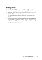
Dell PowerEdge R905 Installation and Troubleshooting Guide (.htm) - Page 24
Installation and, Troubleshooting Guide, User's Guide, respective connectors on the system back panel. - power
 |
View all Dell PowerEdge R905 manuals
Add to My Manuals
Save this manual to your list of manuals |
Page 24 highlights
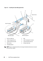
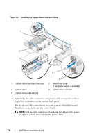
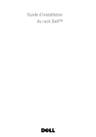
Figure 1-9. Installing the System Status Indicator Cable 1 2 3 4 1 system status indicator cable plug 3 release latch 5 system status indicator slot 5 2 strain-relief loops (1 per power supply, if available) 4 system status indicator 4 Attach the I/O cable connectors and power cable connectors to their respective connectors on the system back panel. For details on cable connections, see your system's Installation and Troubleshooting Guide and the User's Guide. NOTE: Use the strain-relief loops (if available) on the back of the power supplies to provide strain relief for the power cables. 22 Dell™ Rack Installation Guide
-
 1
1 -
2
-
3
-
4
-
5
-
6
-
7
-
8
-
9
-
10
-
11
-
12
-
13
-
14
-
15
-
16
-
17
-
18
-
 19
19 -
 20
20 -
 21
21 -
 22
22 -
 23
23 -
 24
24 -
 25
25 -
 26
26 -
 27
27 -
 28
28 -
 29
29 -
30
-
31
-
32
-
33
-
34
-
35
-
36
-
37
-
38
-
39
-
40
-
41
-
42
-
43
-
44
-
45
-
46
-
47
-
48
-
49
-
50
-
51
-
52
-
53
-
54
-
55
-
56
-
57
-
58
-
59
-
60
-
61
-
62
-
63
-
64
-
65
-
66
-
67
-
68
-
69
-
70
-
71
-
72
-
73
-
74
-
75
-
76
-
77
-
78
-
79
-
80
-
81
-
82
-
83
-
84
-
85
-
86
-
87
-
88
-
89
-
90
-
91
-
92
-
93
-
94
-
95
-
96
-
97
-
98
-
99
-
100
-
101
-
102
-
103
-
104
-
105
-
106
-
107
-
108
-
109
-
110
-
111
-
112
-
113
-
114
-
115
-
116
-
117
-
118
-
119
-
120
-
121
-
122
-
123
-
124
-
125
-
126
-
127
-
128
-
129
-
130
-
131
-
132
-
133
-
134
-
135
-
136
-
137
-
138
-
139
-
140
-
141
-
142
 |
 |

22
Dell™ Rack Installation Guide
Figure 1-9.
Installing the System Status Indicator Cable
4
Attach the I/O cable connectors and power cable connectors to their
respective connectors on the system back panel.
For details on cable connections, see your system’s
Installation and
Troubleshooting Guide
and the
User’s Guide
.
NOTE:
Use the strain-relief loops (if available) on the back of the power
supplies to provide strain relief for the power cables.
1
system status indicator cable plug
2
strain-relief loops
(1 per power supply, if available)
3
release latch
4
system status indicator
5
system status indicator slot
3
1
4
2
5