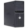
Dell PowerEdge SC430 Installation Guide
Dell PowerEdge SC430 Manual
 |
View all Dell PowerEdge SC430 manuals
Add to My Manuals
Save this manual to your list of manuals |
Dell PowerEdge SC430 manual content summary:
- Dell PowerEdge SC430 | Installation Guide - Page 1
Dell™ PowerEdge™ SC430 Systems Installation and Troubleshooting Guide Introduction Indicators, Messages, and Codes Running the System Diagnostics Troubleshooting Your System Installing System Options Installing Drives Service Only Parts Replacement Procedures Getting Help Jumpers and Connectors I/O - Dell PowerEdge SC430 | Installation Guide - Page 2
Dell™ PowerEdge™ SC430 Systems Installation and Troubleshooting Guide Jumpers-A General Explanation System Board Jumpers System Board system's jumpers. System Board Jumpers Figure A-2 shows the location of the configuration jumpers on the system board. Table A-1 lists the jumpers settings. Figure - Dell PowerEdge SC430 | Installation Guide - Page 3
Auxiliary power LED. System battery Card-cage cooling fan Memory modules (4) Processor fan connector Floppy drive Front-panel switches and indicators Expansion card slots: l one PCI Express [x8] l one PCI Express [x1] l one PCI Express [x4] l two 32-bit/33-MHz PCI IDE INTRUDER POWER P1 POWER P2 - Dell PowerEdge SC430 | Installation Guide - Page 4
Guide. The password jumper enables these password features or disables them and clears any password(s) currently in use. CAUTION: Only trained service disabled (erased) until the system boots with the password jumper plug See "Closing the System" in "Troubleshooting Your System". 10. Reconnect the - Dell PowerEdge SC430 | Installation Guide - Page 5
Dell™ PowerEdge™ SC430 Systems Installation and Troubleshooting Guide I/O Connectors Video Connector USB Connector Integrated NIC Connector Network Cable Requirements I/O Connectors I/O connectors are the gateways that the system uses to communicate with external devices, such as a keyboard - Dell PowerEdge SC430 | Installation Guide - Page 6
N/A No connection USB Connector The system's USB connector supports USB-compliant peripherals such as keyboards, mice, and printers and may also support USB-compliant devices such as diskette drives, CD drives, and compact flash drives. Figure B-3 illustrates the pin numbers for the USB connector - Dell PowerEdge SC430 | Installation Guide - Page 7
Network Cable Requirements The NIC supports a UTP Ethernet cable equipped with a standard RJ45-compatible plug. Observe the following cabling restrictions. NOTICE: To avoid line interference, voice and data lines must be in separate - Dell PowerEdge SC430 | Installation Guide - Page 8
Page Dell™ PowerEdge™ SC430 Systems Installation and Troubleshooting Guide Notes, problem. CAUTION: A CAUTION indicates a potential for property damage, personal injury, or death. Abbreviations and Acronyms For a complete list of abbreviations and acronyms, see the Glossary in your User's Guide - Dell PowerEdge SC430 | Installation Guide - Page 9
™ PowerEdge™ SC430 Systems Installation and Troubleshooting Guide Other Information You May Need The following upgrade options are available for your system: l Processor l Memory l PCI or PCIe expansion cards l SATA hard drives l SCSI hard drives l SCSI controller l Optical drive l Tape backup drive - Dell PowerEdge SC430 | Installation Guide - Page 10
Indicator Code The system is off. The system is powering up. If the hard-drive indicator is off, the power supply may need to be replaced. Solid amber Solid green If the hard-drive indicator is on, the system board is faulty. Check the diagnostic indicators to see if the specific problem is - Dell PowerEdge SC430 | Installation Guide - Page 11
. Indicates hard-drive activity. Indicates network is linked. The front panel also incorporates two USB 2.0 connectors. See Figure 2-1. Diagnostics Indicator Codes The four diagnostic indicator lights on the system front panel display error codes during system startup. Table 2-2 lists the causes - Dell PowerEdge SC430 | Installation Guide - Page 12
is off, the NIC is not connected to the network or the NIC is disabled in the System Setup program. See "Using the System Setup Program" in your User's Guide. 1000-Mbps connection 100-Mbps connection 10-Mbps connection Power Supply Features The voltage selection switch on the back panel of - Dell PowerEdge SC430 | Installation Guide - Page 13
Error Previously Detected One or more memory modules might be See "Troubleshooting System Memory" and improperly seated or faulty, or the system "Troubleshooting Your System." board may be faulty. If the problem persists, see "Getting Help." Attachment failed to respond The diskette or hard-drive - Dell PowerEdge SC430 | Installation Guide - Page 14
an uncorrectable read error. See "Troubleshooting a Diskette Drive," "Troubleshooting SATA Hard Drives," or "Troubleshooting SCSI Hard Drives" in "Troubleshooting Your System." The system encountered a problem while trying to configure an expansion card or integrated on-board devices. If the - Dell PowerEdge SC430 | Installation Guide - Page 15
error message appears again, see "Troubleshooting System Memory" in "Troubleshooting Your System." If the problem persists, see "Getting Help." If the diskette drive is your boot device, ensure that a bootable disk is in the drive. If the hard drive is your boot device, ensure that the hard drive - Dell PowerEdge SC430 | Installation Guide - Page 16
Seek error "Troubleshooting SATA Hard Drives," or "Troubleshooting SCSI Hard Drives" in "Troubleshooting Your System." Shutdown failure A chip on the system board might be malfunctioning. Run the system diagnostics. See "Running the System Diagnostics." The file being copied is too large for - Dell PowerEdge SC430 | Installation Guide - Page 17
check failure Keyboard controller not detected Video memory test failure Screen initialization failure Screen-retrace test failure Video ROM search failure No timer tick Shutdown test failure Gate A20 failure Unexpected interrupt in protected mode See "Troubleshooting Expansion Cards" in - Dell PowerEdge SC430 | Installation Guide - Page 18
Dell™ PowerEdge™ SC430 Systems Installation and Troubleshooting Guide Using Server Administrator Diagnostics System Diagnostics Features When to Use the System Diagnostics Running the System Diagnostics System Diagnostics Testing Options Using the Custom Test Options If you experience a problem - Dell PowerEdge SC430 | Installation Guide - Page 19
Diagnostics Testing Options Testing Option Function Express Test Performs a quick check of the system. This option runs device tests that do not require user interaction. Use this option to quickly identify the source of your problem the Customize window lists devices Errors - Displays any errors - Dell PowerEdge SC430 | Installation Guide - Page 20
Troubleshooting Power Supplies Troubleshooting System Cooling Problems Troubleshooting System Memory Troubleshooting a Diskette Drive Troubleshooting a CD Drive Troubleshooting an IDE Tape Drive Troubleshooting an Internal SCSI Tape Drive Troubleshooting SCSI Hard Drives Troubleshooting SATA Hard - Dell PowerEdge SC430 | Installation Guide - Page 21
Server Administrator Diagnostics" in "Running the System Diagnostics." If the tests run successfully, the problem is not related to video hardware. If the tests fail, see "Getting Help." Troubleshooting the Keyboard Problem l System message indicates a problem with the keyboard. l Keyboard is not - Dell PowerEdge SC430 | Installation Guide - Page 22
, replace the faulty mouse. See "Getting Help." 4. Enter the System Setup program and ensure that the USB ports are enabled. See "Using the System Setup Program" in your User's Guide. If the problem is not resolved, see "Getting Help." Troubleshooting Basic I/O Functions Problem l Error message - Dell PowerEdge SC430 | Installation Guide - Page 23
system and the USB device. If the problem is resolved, replace the USB device. See "Getting Help." If the problem persists, see "Getting Help." Troubleshooting a NIC Problem l NIC cannot communicate with network. Action 1. Run the appropriate online diagnostic test. See "Using Server Administrator - Dell PowerEdge SC430 | Installation Guide - Page 24
electrical outlet. 2. Press the power button to ground the system board. 3. If you have installed the way. 2. Ensure that no tools or extra parts are left inside the system. 3. Reinstall the system Guide for details. NOTE: If a setup password has been assigned by someone else, contact your network - Dell PowerEdge SC430 | Installation Guide - Page 25
SCSI hard drives must be connected to a controller card. They also provide space for an optional optical and diskette drive, or an optional tape backup unit (TBU). Power is supplied to the system board and internal peripherals through a single nonredundant power supply. Removing and Replacing the - Dell PowerEdge SC430 | Installation Guide - Page 26
above and snap the insert into place. Figure 4-4. Removing and Replacing the Front Drive Bezel Insert Troubleshooting a Wet System Problem l Liquid spilled on the system. l Excessive humidity. Action CAUTION: Only trained service technicians are authorized to remove the system cover and access any - Dell PowerEdge SC430 | Installation Guide - Page 27
are properly installed: l Expansion cards l Power supplies l Fans l Optional installed drives l Processor heat sink 3. Ensure that all cables are properly connected. 4. Close the system. See "Closing the System." 5. Run the system board tests in the system diagnostics. See "Running the System - Dell PowerEdge SC430 | Installation Guide - Page 28
Troubleshooting Power Supplies Problem l Power-supply fault indicator is blinking amber. Action CAUTION: Only trained service technicians are authorized to remove the system cover and access any of the components inside the system. Before performing any procedure, see your Product Information Guide - Dell PowerEdge SC430 | Installation Guide - Page 29
System." If the replacement fan does not operate, see "Getting Help." Troubleshooting System Memory Problem l Faulty memory module. l Faulty system board. l Diagnostic indicators or system messages indicate a memory-related error. Action CAUTION: Only trained service technicians are authorized to - Dell PowerEdge SC430 | Installation Guide - Page 30
f in step 10 for each memory module installed. If the problem persists, see "Getting Help." Troubleshooting a Diskette Drive Problem l Diagnostic indicators or error messages indicate a diskette drive (optional) problem. Action CAUTION: Only trained service technicians are authorized to remove the - Dell PowerEdge SC430 | Installation Guide - Page 31
Help." Troubleshooting a CD Drive Problem l System cannot read data from a CD in an IDE CD drive. l Diagnostic indicators or system messages indicate a CD-related failure. l CD drive indicator, if applicable, does not blink during boot. l A Recording tab does not appear in the Properties window of - Dell PowerEdge SC430 | Installation Guide - Page 32
capabilities, see support.microsoft.com. Troubleshooting an IDE Tape Drive Problem l System cannot read data from a tape in an IDE tape drive. l Diagnostic indicators or system messages indicate a tape drive-related failure. l Tape drive indicator (if applicable) does not blink during boot. Action - Dell PowerEdge SC430 | Installation Guide - Page 33
"Getting Help." Troubleshooting an Internal SCSI Tape Drive Problem l Diagnostic indicators or system messages indicate a hard drive or expansion card problem l Defective tape drive. l Defective tape cartridge. l Missing or corrupted tape-backup software or tape drive device driver. l Defective SCSI - Dell PowerEdge SC430 | Installation Guide - Page 34
Problem l Diagnostic indicators or system messages indicate a hard drive or expansion card problem l Device driver error. l Hard drive not recognized by the system. Action CAUTION: Only trained service technicians are authorized to remove the system cover and access any of the components inside the - Dell PowerEdge SC430 | Installation Guide - Page 35
. 10. Format and partition the hard drive. See the operating system documentation. 11. If possible, restore the files to the drive. If the problem persists, see "Getting Help." Troubleshooting Expansion Cards NOTE: When troubleshooting an expansion card, see the documentation for your operating - Dell PowerEdge SC430 | Installation Guide - Page 36
." c. Reinstall one of the expansion cards. d. Close the system. See "Closing the System." e. Run the appropriate diagnostic test. If the tests fail, see "Getting Help." Troubleshooting the Microprocessor Problem l Error message indicates a microprocessor problem. l A heat sink is not installed - Dell PowerEdge SC430 | Installation Guide - Page 37
Back to Contents Page Installing System Options Dell™ PowerEdge™ SC430 Systems Installation and Troubleshooting Guide Memory Microprocessor Expansion Cards Power Supply Cooling Fans System Battery Memory The four memory module connectors on the system board can accommodate from 256 MB to 4 GB of 533 - Dell PowerEdge SC430 | Installation Guide - Page 38
use by the operating system. Installing a Memory Module CAUTION: Only trained service technicians are authorized to remove the system cover and access any of the components inside the system. Before performing any procedure, see your Product Information Guide for complete information about safety - Dell PowerEdge SC430 | Installation Guide - Page 39
in speed and functionality, you can upgrade the processor. The processor and its associated cache memory are contained in a Land Grid Array (LGA) package that is installed in a socket on the system board. Removing the Processor CAUTION: Only trained service technicians are authorized to remove the - Dell PowerEdge SC430 | Installation Guide - Page 40
that the latch does not quickly open and strike the processor or system board. 6. Carefully pivot the retention latch away from the processor. NOTICE: is ready for the new processor. Replacing the Processor 1. Ensure that the contacts on the bottom of the replacement processor are free from dirt or - Dell PowerEdge SC430 | Installation Guide - Page 41
system. See "Closing the System" in "Troubleshooting Your System." 10. Reconnect the system to the electrical outlet, and turn on the system and attached peripherals. Expansion Cards The system board can accommodate five expansion cards (two 5-V, half-length 32-bit, 33-MHz PCI, one 2.5-Gb/sec PCIe - Dell PowerEdge SC430 | Installation Guide - Page 42
System" in "Troubleshooting Your System." 9. Reconnect the system to the electrical outlet, and turn on the system and attached peripherals. 10. Remove the card's device driver from the operating system. Power Supply Removing the Power Supply CAUTION: Only trained service technicians are authorized - Dell PowerEdge SC430 | Installation Guide - Page 43
the cables from the system board and drives. You must route these cables properly when you replace them to prevent their being pinched or crimped. 5. Remove the IDE, I/O panel, and SATA cables attached to the routing clamps on the side of the power supply. 6. Using a #2 Phillips screwdriver, remove - Dell PowerEdge SC430 | Installation Guide - Page 44
outlet. 2. Open the system. See "Opening the System" in "Troubleshooting Your System." 3. Disconnect the fan's power cable from the system board. See Figure A-3. 4. Depending on which fan you are removing: a. If you are removing the smaller card cage fan, press the single release tab that attaches - Dell PowerEdge SC430 | Installation Guide - Page 45
pressing on the tab. See Figure 5-6. Figure 5-6. Replacing the Battery 6. Install the new battery with the side labeled "+" facing up, and press down until it snaps into place. 7. Close the system. See "Closing the System" in "Troubleshooting Your System." 8. Reconnect the system to the electrical - Dell PowerEdge SC430 | Installation Guide - Page 46
Contents Page Installing Drives Dell™ PowerEdge™ SC430 Systems Installation and Troubleshooting Guide General Installation Guidelines Installing SATA or SCSI Hard Drives Installing a SCSI Controller Card Installing a Diskette Drive Installing 5.25-Inch Optical and Tape Drives The drive bays in your - Dell PowerEdge SC430 | Installation Guide - Page 47
card. The system can also boot from an external USB diskette or optical drive. See "Using the System Setup Program" in your User's Guide. Installing SATA or SCSI Hard Drives Your system contains up to two SATA or SCSI non-hot-plug hard drives. The integrated SATA controller supports two SATA hard - Dell PowerEdge SC430 | Installation Guide - Page 48
and Installing a Hard Drive in the Guide Bracket Assembly 7. Connect the power cable to the drive. See Figure 6-2 or Figure 6-3. 8. Connect the interface cable to the drive: l Connect SATA hard drives to the SATA0 (first drive) and SATA2 (second drive) connectors on the system board. See Figure - Dell PowerEdge SC430 | Installation Guide - Page 49
your User's Guide. 12. Partition and logically format your drive before proceeding to the next step. See the documentation for your operating system for instructions. 13. Test the hard drive by running the system diagnostics. See "Running the System Diagnostics." 14. If the drive you just installed - Dell PowerEdge SC430 | Installation Guide - Page 50
the FLOPPY connector on the system board. See Figure 6-6 and Figure A-3. 12. Close the system. See "Closing the System" in "Troubleshooting Your System." 13. Replace the front drive bezel. See "Removing and Replacing the Front Drive Bezel" in "Troubleshooting Your System." 14. Reconnect the system - Dell PowerEdge SC430 | Installation Guide - Page 51
the system from the electrical outlet. 4. Open the system. See "Opening the System" in "Troubleshooting Your System." 5. Remove the front drive bezel. See "Removing and Replacing the Front Drive Bezel" in "Troubleshooting Your System." 6. If necessary, remove the front-panel insert for the empty - Dell PowerEdge SC430 | Installation Guide - Page 52
IDE connector on the system board to the drive. See Figure 6-8 and Figure A-3. 10. Close the system. See "Closing the System" in "Troubleshooting Your System." 11. Replace the front drive bezel. See "Removing and Replacing the Front Drive Bezel" in "Troubleshooting Your System." 12. Reconnect the - Dell PowerEdge SC430 | Installation Guide - Page 53
Contents Page Service Only Parts Replacement Procedures Dell™ PowerEdge™ SC430 Systems Installation and Troubleshooting Guide Before You Begin Recommended Tools Removing and Replacing the Bezel I/O Panel Chassis Intrusion Switch System Board Before You Begin CAUTION: Only trained service technicians - Dell PowerEdge SC430 | Installation Guide - Page 54
" in "Installing System Options." 5. Reinstall the processor heat sink and shroud assembly. See "Replacing the Processor" in "Installing System Options." 6. Close the system. See "Closing the System" in "Troubleshooting Your System." 7. Reconnect the system to the electrical outlet, and turn on the - Dell PowerEdge SC430 | Installation Guide - Page 55
Replacing the I/O Panel CAUTION: Only trained service technicians are authorized to remove the system cover and access any of the components inside the system. Before performing any procedure, see your Product Information Guide for complete information about safety precautions, working inside the - Dell PowerEdge SC430 | Installation Guide - Page 56
and attached peripherals, and disconnect the system from the electrical outlet. 2. Open the system. See "Opening the System" in "Troubleshooting Your System." 3. Disconnect the following cables from the system board. See Figure A-3. l Two power-supply cables from the POWER P1 and POWER P2 connectors - Dell PowerEdge SC430 | Installation Guide - Page 57
hard-drive data cable(s) from the SATA connector(s) 4. Remove all expansion cards and any attached cables. See "Removing an Expansion Card" in "Installing System Options." 5. Remove all memory modules. See "Removing a Memory sink pivot mount to the system board. NOTICE: To prevent damaging the - Dell PowerEdge SC430 | Installation Guide - Page 58
the System Board." See Figure A-3. l Two power-supply cables to the POWER P1 and POWER P2 Card cage cooling fan cable to the CARD CAGE COOLING FAN connector l If applicable, SATA hard-drive data cable(s) to the SATA connector(s) 8. Close the system. See "Closing the System" in "Troubleshooting - Dell PowerEdge SC430 | Installation Guide - Page 59
Page Getting Help Dell™ PowerEdge™ SC430 Systems Installation and Troubleshooting Guide Technical Assistance Dell Enterprise Training and Certification Problems With Your Order Product Information Returning Items for Warranty Repair or Credit Before You Call Contacting Dell Technical Assistance If - Dell PowerEdge SC430 | Installation Guide - Page 60
is available 24 hours a day, 7 days a week, to answer your questions about Dell hardware. Our technical support staff use computer-based diagnostics to provide fast, accurate answers. To contact Dell's technical support service, see "Before You Call" and then see the contact information for your - Dell PowerEdge SC430 | Installation Guide - Page 61
network card: Programs and versions: See your operating system documentation to determine the contents of the system's start-up files. If possible, print each file. Otherwise, record the contents of each file before calling Dell. Error message, beep code, or diagnostic code: Description of problem - Dell PowerEdge SC430 | Installation Guide - Page 62
) E-mail for French-speaking Customers: support.euro.dell.com/be/fr/emaildell/ International Access Code: 00 Country Code: 32 Technical Support for Inspiron XPS computers only Technical Support for all other Dell computers Technical Support Fax City Code: 2 Customer Care Corporate Sales Fax - Dell PowerEdge SC430 | Installation Guide - Page 63
bus., government) Spare Parts Sales & Extended Service Sales Cayman Islands General Support Chile (Santiago) Country Code: 56 Sales, Customer Support, and Technical Support City Code: 2 Technical Support website: support.dell.com.cn Technical Support E-mail: [email protected] Customer Care - Dell PowerEdge SC430 | Installation Guide - Page 64
Code: 00 Country Code: 30 Technical Support Gold Service Technical Support Switchboard Gold Service Switchboard Sales Fax Grenada General Support Guatemala General Support Guyana General Support Website: support.ap.dell.com Technical Support E-mail: [email protected] Technical Support - Dell PowerEdge SC430 | Installation Guide - Page 65
(Home and Small Business) Website: support.euro.dell.com E-mail: [email protected] Technical Support for Inspiron XPS computers only Technical Support for all other Dell computers Ireland (Cherrywood) International Access Code: 16 U.K. Technical Support (dial within U.K. only) Home - Dell PowerEdge SC430 | Installation Guide - Page 66
Sales Customer Technical Support Mexico Sales International Access Code: 00 Country Code: 52 Customer Service Main Montserrat General Support Netherlands Antilles General Support Website: support.euro.dell.com Technical Support for Inspiron XPS computers only Technical Support for all - Dell PowerEdge SC430 | Installation Guide - Page 67
, Inspiron, and Electronics and Accessories) Technical Support (OptiPlex, Latitude, and Dell Precision) International Access Code: 005 Technical Support (PowerApp, PowerEdge, PowerConnect, and PowerVault) Country Code: 65 Customer Service (Penang, Malaysia) Transaction Sales Corporate Sales - Dell PowerEdge SC430 | Installation Guide - Page 68
Sales Corporate Sales Website: support.ap.dell.com Thailand Technical Support (OptiPlex, Latitude, and Dell Precision) Technical Support (PowerApp, PowerEdge, PowerConnect, and PowerVault) International Access Code: 001 Customer Service (Penang, Malaysia) Country Code: 66 Corporate Sales - Dell PowerEdge SC430 | Installation Guide - Page 69
Country Code: 1 Printers and Projectors Technical Support Public (government, education, and healthcare) Customer Service and Technical Support Employee Purchase Program (EPP) Customers Dell Sales Dell Outlet Store (Dell refurbished computers) Software and Peripherals Sales Spare Parts Sales
-
 1
1 -
 2
2 -
 3
3 -
 4
4 -
 5
5 -
 6
6 -
 7
7 -
8
-
9
-
10
-
11
-
12
-
13
-
14
-
15
-
16
-
17
-
18
-
19
-
20
-
21
-
22
-
23
-
24
-
25
-
26
-
27
-
28
-
29
-
30
-
31
-
32
-
33
-
34
-
35
-
36
-
37
-
38
-
39
-
40
-
41
-
42
-
43
-
44
-
45
-
46
-
47
-
48
-
49
-
50
-
51
-
52
-
53
-
54
-
55
-
56
-
57
-
58
-
59
-
60
-
61
-
62
-
63
-
64
-
65
-
66
-
67
-
68
-
69
 |
 |
Dell™ PowerEdge™ SC430 Systems Installation and Troubleshooting Guide
Introduction
Indicators, Messages, and Codes
Running the System Diagnostics
Troubleshooting Your System
Installing System Options
Installing Drives
Service Only Parts Replacement Procedures
Getting Help
Jumpers and Connectors
I/O Connectors
Notes, Notices, and Cautions
Abbreviations and Acronyms
For a complete list of abbreviations and acronyms, see the Glossary in your
User's Guide
.
Information in this document is subject to change without notice.
© 2005 Dell Inc. All rights reserved.
Reproduction in any manner whatsoever without the written permission of Dell Inc.
is strictly forbidden.
Trademarks used in this text:
Dell
, the
DELL
logo,
Inspiron
,
Dell Precision
,
Dimension
,
OptiPlex
,
Latitude, PowerEdge, PowerVault, PowerConnect, DellNet
,
and PowerApp
are trademarks of
Dell Inc.;
Microsoft
and
Windows
are registered trademarks and
Windows Server
is a trademark of Microsoft Corporation.;
EMC
is a registered trademark of EMC Corporation.
Other trademarks and trade names may be used in this document to refer to either the entities claiming the marks and names or their products. Dell Inc. disclaims any
proprietary interest in trademarks and trade names other than its own.
Initial release: 13 Apr 2005
NOTE:
A NOTE indicates important information that helps you make better use of your computer.
NOTICE:
A NOTICE indicates either potential damage to hardware or loss of data and tells you how to avoid the problem.
CAUTION:
A CAUTION indicates a potential for property damage, personal injury, or death.