Dell R710 Technical Guide - Page 19
LCD Control Panel - system interrupt controller
 |
UPC - 884116025849
View all Dell R710 manuals
Add to My Manuals
Save this manual to your list of manuals |
Page 19 highlights
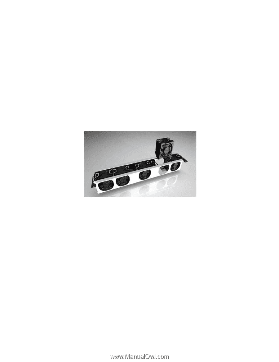
Dell 4.8.2 ReadyRails Static Rails ReadyRailsTM Static Rails for 4-post and 2-post racks support the following: Toolless installation in 19‖ EIA-310-E compliant square or unthreaded round hole 4-post racks including all generations of Dell racks Tooled installation in 19‖ EIA-310-E compliant threaded hole 4-post and 2-post racks See section 14 for more details. 4.9 Fans Five hot-swappable fans are mounted in a fan gantry that is located in the chassis between the hard drive bay and the processors. See Figure 7. Each fan has a blind mate 2x2 connector that plugs directly into the planar. There is an additional fan integrated in each power supply to cool the power supply subsystem and also provide additional cooling for the whole system. Single processor configurations have four fans populated. Figure 7. Fan Gantry The Embedded Server Management logic in the system monitors the speed of the fans. A fan failure or over-temperature in the system results in a notification by iDRAC6. All system fans are pulse-width modulated fans. Redundant cooling is supported. 4.10 LCD Control Panel The LCD control panel is located on the front of the system chassis to provide user access to switches, display, and I/O interfaces. See Figure 8. The control panel includes the following features: ACPI-compliant power button with an integrated green power LED (controlled by iDRAC6) 128x20 pixel LCD with controls: o Two navigation buttons o Select button o System ID button Non-maskable Interrupt (NMI) button (recessed) Ambient temperature sensor PowerEdge R710 Technical Guide 19
-
 1
1 -
2
-
3
-
4
-
5
-
6
-
7
-
8
-
9
-
10
-
11
-
12
-
13
-
 14
14 -
 15
15 -
 16
16 -
 17
17 -
 18
18 -
 19
19 -
 20
20 -
 21
21 -
 22
22 -
 23
23 -
 24
24 -
25
-
26
-
27
-
28
-
29
-
30
-
31
-
32
-
33
-
34
-
35
-
36
-
37
-
38
-
39
-
40
-
41
-
42
-
43
-
44
-
45
-
46
-
47
-
48
-
49
-
50
-
51
-
52
-
53
-
54
-
55
-
56
-
57
-
58
-
59
-
60
-
61
-
62
-
63
 |
 |