Dell R710 Technical Guide - Page 48
Rack Information - server rails
 |
UPC - 884116025849
View all Dell R710 manuals
Add to My Manuals
Save this manual to your list of manuals |
Page 48 highlights
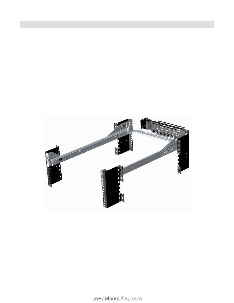
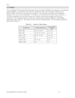
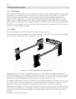
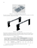
Dell 14 Rack Information 14.1 Overview The ReadyRails™ sliding and static rail systems for the R710 provide toolless support for 4-post racks with square or unthreaded round mounting holes including all generations of Dell racks. Both rail systems support tooled mounting in 4-post threaded racks (an optional adapter brackets kit is required for the sliding rails). The static rails also providing tooled mounting support for 2-post (Telco) racks for added versatility. The optional cable management arm (CMA) can be mounted on either the left or right side of the sliding rails without the use of tools for fast and easy deployment. The R710 is not compatible with any other Dell rails including previous generation rails, but it does use the same static rails as the R610. 14.2 Rails The rail offerings for the R710 consist of two types: sliding and static. The sliding rails allow the system to be fully extended out of the rack for service and are available with or without the optional cable management arm (CMA). Figure 11. R710 Sliding Rails with Optional CMA Sliding rail kits can be used in a threaded-hole rack only if threaded rack adapter brackets are installed (see Figure 12). The threaded rack adapter brackets are first mounted to the EIA flanges in the rack, and the sliding rails are mounted into the brackets. The design of the brackets has been optimized to limit the forward shift of the system in the rack to only 17.3 mm. The adapter brackets kit includes six brackets to accommodate different rail lengths, plus four sets of custom screws in common thread sizes. A detailed Getting Started Guide is included in the kit along with directions for installing the brackets and mounting the rails into the brackets. Depending on the depth of the rack used, it may be necessary to remove the server's bezel in order to close the door of the rack. A minimum of 58 mm is needed between the back surface of the door panel and the front face of the EIA flange for the front door to close with the 11G server bezel installed. PowerEdge R710 Technical Guide 48
-
 1
1 -
2
-
3
-
4
-
5
-
6
-
7
-
8
-
9
-
10
-
11
-
12
-
13
-
14
-
15
-
16
-
17
-
18
-
19
-
20
-
21
-
22
-
23
-
24
-
25
-
26
-
27
-
28
-
29
-
30
-
31
-
32
-
33
-
34
-
35
-
36
-
37
-
38
-
39
-
40
-
41
-
42
-
 43
43 -
 44
44 -
 45
45 -
 46
46 -
 47
47 -
 48
48 -
 49
49 -
 50
50 -
 51
51 -
 52
52 -
 53
53 -
54
-
55
-
56
-
57
-
58
-
59
-
60
-
61
-
62
-
63
 |
 |