Dell Vostro 15 3568 Vostro 15-3568 Owners Manual - Page 29
System fan, Removing the system fan
 |
View all Dell Vostro 15 3568 manuals
Add to My Manuals
Save this manual to your list of manuals |
Page 29 highlights
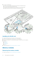
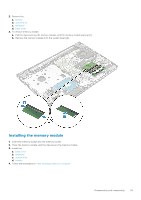
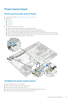
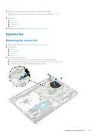
2. Tighten the four captive screws to secure it to the system board. NOTE: Secure the screws in the order of the callout numbers [1, 2, 3, 4]. 3. Install the: a. base cover b. keyboard c. optical drive d. battery 4. Follow the procedures in After working inside your computer. System fan Removing the system fan 1. Follow the procedure in Before working inside your computer. 2. Remove the: a. battery b. optical drive c. keyboard d. base cover 3. To remove the system fan: a. Disconnect the system fan connector cable from the system board [1]. b. Remove the two M2L5 screws that secure the system fan to the computer [2]. c. Lift and remove the system fan from the chassis [3]. Disassembly and reassembly 29
-
 1
1 -
2
-
3
-
4
-
5
-
6
-
7
-
8
-
9
-
10
-
11
-
12
-
13
-
14
-
15
-
16
-
17
-
18
-
19
-
20
-
21
-
22
-
23
-
 24
24 -
 25
25 -
 26
26 -
 27
27 -
 28
28 -
 29
29 -
 30
30 -
 31
31 -
 32
32 -
 33
33 -
 34
34 -
35
-
36
-
37
-
38
-
39
-
40
-
41
-
42
-
43
-
44
-
45
-
46
-
47
-
48
-
49
-
50
-
51
-
52
-
53
-
54
-
55
-
56
-
57
-
58
-
59
-
60
-
61
-
62
-
63
-
64
-
65
-
66
-
67
-
68
-
69
-
70
-
71
-
72
-
73
-
74
-
75
-
76
-
77
-
78
-
79
-
80
-
81
 |
 |

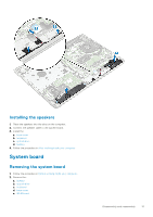
2.
Tighten the four captive screws to secure it to the system board.
NOTE:
Secure the screws in the order of the callout numbers [1, 2, 3, 4].
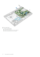
3.
Install the:
a.
base cover
b.
keyboard
c.
optical drive
d.
battery
4.
Follow the procedures in
After working inside your computer
.
System fan
Removing the system fan
1.
Follow the procedure in
Before working inside your computer
.
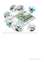
2.
Remove the:
a.
battery
b.
optical drive
c.
keyboard
d.
base cover
3.
To remove the system fan:
a.
Disconnect the system fan connector cable from the system board [1].
b.
Remove the two M2L5 screws that secure the system fan to the computer [2].
c.
Lift and remove the system fan from the chassis [3].
Disassembly and reassembly
29