Dell Vostro 3360 Owner's Manual - Page 27
Installing the Display Panel, Removing the Camera Module
 |
View all Dell Vostro 3360 manuals
Add to My Manuals
Save this manual to your list of manuals |
Page 27 highlights
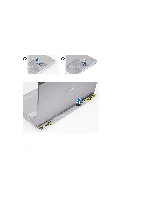
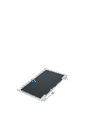
Installing the Display Panel 1. Place the camera cable on the back of the display panel. 2. Connect the display cable to its connector on the display panel. 3. Place the display panel to its original position on the display assembly. 4. Tighten the screws to secure the display panel to the display assembly. 5. Connect the camera cable to camera module. 6. Install : a) display bezel b) display assembly c) display hinge cover d) battery e) palmrest f) keyboard g) access panel 7. Follow the procedures in After Working Inside Your Computer. Removing the Camera Module 1. Follow the procedures in Before Working Inside Your Computer. 2. Remove: a) access panel b) keyboard c) palmrest d) battery e) display hinge cover f) display assembly g) display bezel 3. Disconnect the camera cable from the camera module and remove the camera module from the display assembly. 27
-
 1
1 -
2
-
3
-
4
-
5
-
6
-
7
-
8
-
9
-
10
-
11
-
12
-
13
-
14
-
15
-
16
-
17
-
18
-
19
-
20
-
21
-
 22
22 -
 23
23 -
 24
24 -
 25
25 -
 26
26 -
 27
27 -
 28
28 -
 29
29 -
 30
30 -
 31
31 -
 32
32 -
33
-
34
-
35
-
36
-
37
-
38
-
39
-
40
-
41
-
42
-
43
-
44
-
45
-
46
-
47
-
48
-
49
-
50
-
51
-
52
-
53
-
54
-
55
 |
 |
