Dell Vostro 3905 Dell Vostro 3905 Owners Manual - Page 20
Removing the Input/Output (I/O) Panel
 |
View all Dell Vostro 3905 manuals
Add to My Manuals
Save this manual to your list of manuals |
Page 20 highlights
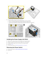
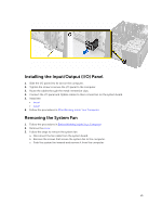
4. Connect the power-switch cable to the connector on the system board. 5. Install the: • bezel • cover 6. Follow the procedures in After Working Inside Your Computer. Removing the Input/Output (I/O) Panel 1. Follow the procedures in Before Working Inside Your Computer. 2. Remove the: • cover • bezel 3. Follow the steps to remove the I/O panel cables: a. Disconnect the I/O panel and FlyWire cables from the system board [1, 3]. b. Un-thread the cables from the metal-retention clips [2, 4]. 4. Follow the steps to remove the I/O panel: a. Remove the screw that secures the I/O panel to the computer. b. Slide the I/O panel outwards and remove it from the computer. 20
-
 1
1 -
2
-
3
-
4
-
5
-
6
-
7
-
8
-
9
-
10
-
11
-
12
-
13
-
14
-
 15
15 -
 16
16 -
 17
17 -
 18
18 -
 19
19 -
 20
20 -
 21
21 -
 22
22 -
 23
23 -
 24
24 -
 25
25 -
26
-
27
-
28
-
29
-
30
-
31
-
32
-
33
-
34
-
35
-
36
-
37
-
38
-
39
 |
 |

4.
Connect the power-switch cable to the connector on the system board.
5.
Install the:
•
bezel
•
cover
6.
Follow the procedures in
After Working Inside Your Computer
.
Removing the Input/Output (I/O) Panel
1.
Follow the procedures in
Before Working Inside Your Computer
.
2.
Remove the:
•
cover
•
bezel
3.
Follow the steps to remove the I/O panel cables:
a.
Disconnect the I/O panel and FlyWire cables from the system board [1, 3].
b.
Un-thread the cables from the metal-retention clips [2, 4].
4.
Follow the steps to remove the I/O panel:
a.
Remove the screw that secures the I/O panel to the computer.
b.
Slide the I/O panel outwards and remove it from the computer.
20