Dell Vostro 5300 Service Manual
Dell Vostro 5300 Manual
 |
View all Dell Vostro 5300 manuals
Add to My Manuals
Save this manual to your list of manuals |
Dell Vostro 5300 manual content summary:
- Dell Vostro 5300 | Service Manual - Page 1
Vostro 5300 Service Manual Regulatory Model: P121G Regulatory Type: P121G001 - Dell Vostro 5300 | Service Manual - Page 2
of data and tells you how to avoid the problem. WARNING: A WARNING indicates a potential for property damage, personal injury, or death. © 2020 Dell Inc. or its subsidiaries. All rights reserved. Dell, EMC, and other trademarks are trademarks of Dell Inc. or its subsidiaries. Other trademarks may be - Dell Vostro 5300 | Service Manual - Page 3
, not by its pins. CAUTION: You should only perform troubleshooting and repairs as authorized or directed by the Dell technical assistance team. Damage due to servicing that is not authorized by Dell is not covered by your warranty. See the safety instructions that shipped with the product or at www - Dell Vostro 5300 | Service Manual - Page 4
disassembly instructions. ESD field service kit when working inside any notebook to obvious, such as intermittent problems or a shortened product Dell products, the sensitivity to static damage is now higher than in previous Dell of damage to recognize and troubleshoot is the intermittent (also called - Dell Vostro 5300 | Service Manual - Page 5
always return the damaged part using the same ESD bag and packaging that the new part arrived in. The ESD bag should be folded over and taped shut and servicing Dell products. In addition, it is critical that technicians keep sensitive parts separate from all insulator parts while performing service - Dell Vostro 5300 | Service Manual - Page 6
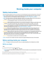
5. Turn on your computer. 6 Working inside your computer - Dell Vostro 5300 | Service Manual - Page 7
2 Major components of Vostro 5300 The following image shows the major components of Vostro 5300. 1. Base cover 2. Battery 3. Fan 4. Wireless-card bracket 5. Wireless card 6. Coin-cell battery 7. Power button with fingerprint reader 8. I/O board Major components of Vostro 5300 7 - Dell Vostro 5300 | Service Manual - Page 8
sink NOTE: Dell provides a list of components and their part numbers for the original system configuration purchased. These parts are available according to warranty coverages purchased by the customer. Contact your Dell sales representative for purchase options. 8 Major components of Vostro 5300 - Dell Vostro 5300 | Service Manual - Page 9
the following tools: • Phillips #0 screwdriver • Phillips #1 screwdriver • Plastic scribe: Recommended for field technicians. NOTE: The #0 screw driver is for screws 0-1 and the #1 screw driver is for screws 2-4. Screw list NOTE: When removing screws from a component, it is recommended to note the - Dell Vostro 5300 | Service Manual - Page 10
Component I/O board Wireless-card bracket Secured to Palm-rest and keyboard assembly Palm-rest and keyboard assembly Screw type M2x3 M2x2.5 Touchpad Palm-rest and keyboard M2x2 assembly Quantity 2 1 4 Screw image Base cover Removing the base cover Prerequisites 1. Follow the procedure in - Dell Vostro 5300 | Service Manual - Page 11
Removing and installing components 11 - Dell Vostro 5300 | Service Manual - Page 12
Steps 1. Loosen the three captive screws that secure the base cover to the palm-rest and keyboard assembly. 2. Remove the four screws (M2x4) that secure the base cover to the palm-rest and keyboard assembly. 3. Starting from the top-left corner, use a plastic scribe to pry the base cover in the - Dell Vostro 5300 | Service Manual - Page 13
Removing and installing components 13 - Dell Vostro 5300 | Service Manual - Page 14
Steps 1. Connect the battery cable to the system board, if applicable. 2. Align the screw holes on the base cover with the screw holes on the palm-rest and keyboard assembly, and then snap the base cover into place. 3. Replace the four screws (M2x4) that secure the base cover to the palm-rest and - Dell Vostro 5300 | Service Manual - Page 15
on or against the battery. • Ensure any screws during the servicing of this product are not lost or misplaced, to prevent accidental puncture contact Dell technical support for assistance. See www.dell.com/contactdell. • Always purchase genuine batteries from www.dell.com or authorized Dell partners - Dell Vostro 5300 | Service Manual - Page 16
Steps 1. Remove the four screws (M2x5) that secure the battery to the palm-rest and keyboard assembly. 2. Disconnect the battery cable from the system board, if applicable. 3. Lift the battery off the palm-rest and keyboard assembly. Installing the 3-cell battery Prerequisites If you are replacing a - Dell Vostro 5300 | Service Manual - Page 17
Next steps 1. Install the base cover. 2. Follow the procedure in After working inside your computer. Removing the 4-cell battery Prerequisites 1. Follow the procedure in Before working inside your computer. 2. Remove the base cover. About this task The following image indicates the location of the - Dell Vostro 5300 | Service Manual - Page 18
Installing the 4-cell battery Prerequisites If you are replacing a component, remove the existing component before performing the installation procedure. About this task The following image indicates the location of the battery and provides a visual representation of the installation procedure. - Dell Vostro 5300 | Service Manual - Page 19
Solid-state drive Removing the solid-state drive Prerequisites 1. Follow the procedure in Before working inside your computer. CAUTION: Solid-state drives are fragile. Exercise care when handling the solid-state drive. CAUTION: To avoid data loss, do not remove the solid-state drive while the - Dell Vostro 5300 | Service Manual - Page 20
About this task The following image indicates the location of the solid-state drive and provides a visual representation of the installation procedure. Steps 1. Lift the mylar that covers the solid-state drive slot. 2. Slide the solid-state drive into the solid-state drive slot. 3. Slide the solid- - Dell Vostro 5300 | Service Manual - Page 21
of the removal procedure. Steps 1. Disconnect the coin-cell battery cable from the system board. 2. Remove the coin-cell battery cable from the routing guide. 3. Peel the coin-cell battery off the palm-rest and keyboard assembly. Installing the coin-cell battery Prerequisites If you are replacing - Dell Vostro 5300 | Service Manual - Page 22
1. Adhere the coin-cell battery to the slot on the palm-rest and keyboard assembly. 2. Route the coin-cell battery cable through the routing guide. 3. Connect the coin-cell battery cable to the system board. Next steps 1. Install the 4-cell battery. 2. Install the 3-cell battery. 3. Install the base - Dell Vostro 5300 | Service Manual - Page 23
Steps 1. Lift the mylar that covers the wireless-card slot. 2. Remove the screw (M2x2.5) that secures the wireless-card bracket to the wireless card and lift the wireless-card bracket off the wireless card. 3. Disconnect the antenna cables from the wireless card. 4. Peel off the tape that secures - Dell Vostro 5300 | Service Manual - Page 24
slot. 3. Connect the antenna cables to the wireless card. The following table provides the antenna-cable color scheme for the wireless card supported by your computer. Table 2. Antenna-cable color scheme Connectors on the wireless card Antenna-cable color Main (white triangle) White Auxiliary - Dell Vostro 5300 | Service Manual - Page 25
Fans Removing the fan Prerequisites 1. Follow the procedure in Before working inside your computer. 2. Remove the base cover. About this task The following images indicate the location of the fans and provide a visual representation of the removal procedure. Steps 1. Peel off the tape that secures - Dell Vostro 5300 | Service Manual - Page 26
Steps 1. Lift the mylar that covers the screw hole on the fan. 2. Align the screw holes on the fan with the screw holes on the system board. 3. Replace the two screws (M2x3) that secure the fan to the system board. 4. Connect the fan cable from the system board. 5. Adhere the tape that secures the - Dell Vostro 5300 | Service Manual - Page 27
that secure the speaker cable to the battery. 3. Note the routing of the speaker cables, and remove the speaker cables from the respective routing guides on the palm-rest and keyboard assembly. 4. Pry the speakers off the palm-rest and keyboard assembly. Installing the speakers Prerequisites If you - Dell Vostro 5300 | Service Manual - Page 28
left and the right speakers into the respective slots on the palm-rest and keyboard assembly. 2. Route the speaker cables through the respective routing guides on the palm-rest and keyboard assembly. 3. Adhere the tapes that secure the speaker cable to the battery. 4. Connect the left and the right - Dell Vostro 5300 | Service Manual - Page 29
Removing and installing components 29 - Dell Vostro 5300 | Service Manual - Page 30
Steps 1. Lift the mylar that covers the display cable on the system board. 2. Open the latch and disconnect the display cable from the system board. 3. Remove the two screws (M2x2) that secure the left hinge to the palm-rest and keyboard assembly. 4. Remove the screw (M2x2) that secures the right - Dell Vostro 5300 | Service Manual - Page 31
Installing the display assembly Prerequisites If you are replacing a component, remove the existing component before performing the installation procedure. About this task The following images indicate the location of the display assembly and provide a visual representation of the installation - Dell Vostro 5300 | Service Manual - Page 32
Steps 1. Place the display assembly on a clean surface. 2. Align and place the palm-rest and keyboard assembly at an angle with the display assembly. 3. Align the screw holes on the display hinges with the screw holes on the palm-rest and keyboard assembly. 4. Replace the screw (M2x2) that secures - Dell Vostro 5300 | Service Manual - Page 33
2. Remove the base cover. 3. Remove the 4-cell battery. 4. Remove the 3-cell battery. About this task The following image indicates the location of touchpad and provides a visual representation of the removal procedure. Steps 1. Peel the tape that secures the speaker cables to the touchpad bracket. - Dell Vostro 5300 | Service Manual - Page 34
Steps 1. Align and place the touchpad into the slot on the palm-rest and keyboard assembly. 2. Replace the two (M2x2) screws that secure the touchpad to the palm-rest and keyboard assembly. 3. Adhere the tapes that secure the touchpad to the palm-rest and keyboard assembly. 4. Connect the touchpad - Dell Vostro 5300 | Service Manual - Page 35
Steps 1. Peel off the mylar that covers the heat sink on the system board. 2. In reverse sequential order (as indicated on the heat sink), loosen the seven captive screws that secure the heat sink to the system board. 3. Lift the heat sink off the system board. Installing the heat sink Prerequisites - Dell Vostro 5300 | Service Manual - Page 36
Steps 1. Align the screw holes on the heat sink with the screw holes on the system board. 2. In sequential order (as indicated on the heat sink), tighten the seven captive screws that secure the heat sink to the system board. 3. Adhere the mylar that covers the heat sink on the system board. Next - Dell Vostro 5300 | Service Manual - Page 37
About this task The following image indicates the location of power-adapter port and provides a visual representation of the removal procedure. Steps 1. Remove the screw (M2x3) that secures the power-adapter port to the system board. 2. Disconnect the power-adapter port cable from the system board. - Dell Vostro 5300 | Service Manual - Page 38
Steps 1. Connect the power-adapter port cable to the system board. 2. Replace the screw (M2x3) that secures the power-adapter port to the palm-rest and keyboard assembly. Next steps 1. Install the base cover. 2. Follow the procedure in After working inside your computer. I/O board Removing the I/O - Dell Vostro 5300 | Service Manual - Page 39
Installing the I/O board Prerequisites If you are replacing a component, remove the existing component before performing the installation procedure. About this task The following image indicates the location of I/O board and provides a visual representation of the installation procedure. Steps 1. - Dell Vostro 5300 | Service Manual - Page 40
is stored in the system board. You must enter the Service Tag in the BIOS setup program after you replace the system board. NOTE: Replacing the system board removes any changes you have made to the - Dell Vostro 5300 | Service Manual - Page 41
If you are replacing a component, remove the existing component before performing the installation procedure. NOTE: Your computer's Service Tag is stored in the system board. You must enter the Service Tag in the BIOS setup program after you replace the system board. NOTE: Replacing the system board - Dell Vostro 5300 | Service Manual - Page 42
Steps 1. Align the system board on the palm-rest and keyboard assembly. 2. Connect the right speaker cable and left speaker cable to the respective connectors on the system board. 3. Connect the coin-cell battery cable to the connector on the system board. 4. Connect the fingerprint-reader cable, - Dell Vostro 5300 | Service Manual - Page 43
Palm-rest and keyboard assembly Removing the palm-rest and keyboard assembly Prerequisites 1. Follow the procedure in Before working inside your computer. 2. Remove the base cover. 3. Remove the 4-cell battery. 4. Remove the 3-cell battery. 5. Remove the wireless card. 6. Remove the speakers. 7. - Dell Vostro 5300 | Service Manual - Page 44
About this task The following image indicates the palm-rest and keyboard assembly and provides a visual representation of the installation procedure. Steps Place the palm-rest and keyboard assembly on a flat surface. Next steps 1. Install the touchpad. 2. Install the power-adapter port. 3. Install - Dell Vostro 5300 | Service Manual - Page 45
8. Remove the display assembly. 9. Remove the power-adapter port. 10. Remove the power button with fingerprint reader. About this task The following image indicates the location of power-adapter port and provides a visual representation of the removal procedure. Steps 1. Peel off the mylar tape - Dell Vostro 5300 | Service Manual - Page 46
Steps 1. Align the power button with fingerprint reader on the palm-rest and keyboard assembly. 2. Connect the power button with fingerprint reader cable to the connector on the palm-rest and keyboard assembly. 3. Adhere the mylar tape that secures the power button with fingerprint reader cable - Dell Vostro 5300 | Service Manual - Page 47
information about the Dell SupportAssist OS Recovery, see Dell SupportAssist OS Recovery User's Guide at www.dell.com/ support. Backup media and recovery options It is recommended to create a recovery drive to troubleshoot and fix problems that may occur with Windows. Dell proposes multiple options - Dell Vostro 5300 | Service Manual - Page 48
ePSA, ePSA or PSA Error Codes Validation Tool Usage Guide Steps 1. User to obtain information from ePSA error windows. 2. Navigate to https://www.dell.com/support/diagnose/Pre-boot-Analysis. 3. Enter error code, validation code, and service tag. Part serial number is optional. 48 Troubleshooting - Dell Vostro 5300 | Service Manual - Page 49
NOTE: For error code, use only the last 3 or 4 digits of the code. (user can enter 0142 or 142 instead of 2000-0142.) 4. Click on Submit once all the necessary information is entered. Results Valid Error Code Example Troubleshooting 49 - Dell Vostro 5300 | Service Manual - Page 50
the above screen which contains information on : • Confirmation of the error code and result outcome • Suggested Part Replacement • If customer is still covered under Dell Warranty • Case reference number if there is an open case under the service tag Invalid Error Code Example 50 Troubleshooting - Dell Vostro 5300 | Service Manual - Page 51
to obtain the QR code from ePSA error screen. 2. User can use any QR code scanner application through the smartphone to scan the QR code. Troubleshooting 51 - Dell Vostro 5300 | Service Manual - Page 52
3. The QR code scanner application will scan the code and automatically generate a link. Click the link to proceed. 52 Troubleshooting - Dell Vostro 5300 | Service Manual - Page 53
take the customer to the Dell Support website which contains information on: • Confirmation of the error code and result outcome • Suggested Part Replacement • If customer is still covered under Dell Warranty • Case reference number if there is an open case under the service tag Troubleshooting 53 - Dell Vostro 5300 | Service Manual - Page 54
are experiencing is an inherent problem with the LCD (screen) of the Dell laptop or with the BIST). How to invoke LCD BIST Test 1. Power off the Dell laptop. 2. Disconnect any peripherals connected to the laptop. Connect only the Esc key to exit. NOTE: Dell ePSA upon launch, initiates a LCD BIST first, - Dell Vostro 5300 | Service Manual - Page 55
improved accuracy in system board failures. NOTE: M-BIST can be manually initiated before POST (Power On Self Test). How to run M- No fault detected with the system board b. AMBER: Indicates a problem with the system board System diagnostic lights Battery-status light Indicates Troubleshooting 55 - Dell Vostro 5300 | Service Manual - Page 56
to WiFi connectivity issues, a WiFi power cycle procedure may be performed. The following procedure provides the instructions on how to conduct a WiFi power cycle: NOTE: Some ISPs (Internet Service Providers) provide a modem/router combo device. Steps 1. Turn off your computer. 2. Turn off the modem - Dell Vostro 5300 | Service Manual - Page 57
resources Information about Dell products and services Dell Support Resource location https://www.dell.com/ Tips Contact Support Online help for operating system Troubleshooting information, user manuals, set up instructions, product specifications, technical help blogs, drivers, software updates - Dell Vostro 5300 | Service Manual - Page 58
catalog. Availability varies by country/region and product, and some services may not be available in your area. To contact Dell for sales, technical support, or customer service issues: 1. Go to https://www.dell.com/support/. 2. Select your country/region from the drop-down menu on the lower
-
 1
1 -
 2
2 -
 3
3 -
 4
4 -
 5
5 -
 6
6 -
 7
7 -
8
-
9
-
10
-
11
-
12
-
13
-
14
-
15
-
16
-
17
-
18
-
19
-
20
-
21
-
22
-
23
-
24
-
25
-
26
-
27
-
28
-
29
-
30
-
31
-
32
-
33
-
34
-
35
-
36
-
37
-
38
-
39
-
40
-
41
-
42
-
43
-
44
-
45
-
46
-
47
-
48
-
49
-
50
-
51
-
52
-
53
-
54
-
55
-
56
-
57
-
58
 |
 |

Vostro 5300
Service Manual
Regulatory Model: P121G
Regulatory Type: P121G001