Dell Vostro 5581 Service Manual
Dell Vostro 5581 Manual
 |
View all Dell Vostro 5581 manuals
Add to My Manuals
Save this manual to your list of manuals |
Dell Vostro 5581 manual content summary:
- Dell Vostro 5581 | Service Manual - Page 1
Dell Vostro 5581 Service Manual Regulatory Model: P77F Regulatory Type: P77F001 - Dell Vostro 5581 | Service Manual - Page 2
of data and tells you how to avoid the problem. WARNING: A WARNING indicates a potential for property damage, personal injury, or death. © 2018 Dell Inc. or its subsidiaries. All rights reserved. Dell, EMC, and other trademarks are trademarks of Dell Inc. or its subsidiaries. Other trademarks may be - Dell Vostro 5581 | Service Manual - Page 3
Contents 1 Working on your computer...6 Safety instructions...6 Turning off your computer - Windows 10...6 Before working inside your computer...6 After working inside your computer...7 2 Technology and components...8 DDR4...8 DDR4 Details...8 Memory Errors...9 USB - Dell Vostro 5581 | Service Manual - Page 4
Installing the memory module...28 Hard drive...29 Removing the 2.5 inch hard drive...29 Installing the 2.5 inch hard drive...31 Solid-state drive...33 Removing the solid-state drive...33 Installing the solid-state drive...34 Speaker...36 Removing the speaker...36 Installing the speaker...37 System - Dell Vostro 5581 | Service Manual - Page 5
cable...79 Removing the display cable...79 Installing the display cable...80 Display back cover...81 Removing the display back cover...81 4 Troubleshooting...82 Enhanced Pre-Boot System Assessment - ePSA diagnostics 82 Running the ePSA Diagnostics...82 Diagnostic LED...83 Battery status lights...83 - Dell Vostro 5581 | Service Manual - Page 6
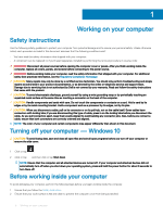
only perform troubleshooting and simple repairs as authorized in your product documentation, or as directed by the online or telephone service and support team. Damage due to servicing that is not authorized by Dell is not covered by your warranty. Read and follow the safety instructions that came - Dell Vostro 5581 | Service Manual - Page 7
3 Turn off your computer. 4 Disconnect all network cables from the computer. CAUTION: To disconnect a network cable, first unplug the cable from your computer and then unplug the cable from the network device. 5 Disconnect your computer and all attached devices from their electrical outlets. 6 Press - Dell Vostro 5581 | Service Manual - Page 8
2 Technology and components NOTE: Instructions provided in this section are applicable on computers just 1.2 volts, compared to DDR3 which requires 1.5 volts of electrical power to operate. DDR4 also supports a new, deep power-down mode that allows the host device to go into standby without needing - Dell Vostro 5581 | Service Manual - Page 9
failure code. If all memory fails, the LCD does not turn on. Troubleshoot for possible memory failure by trying known good memory modules in the memory connection between host computers and peripheral devices like mice, keyboards, external drivers, and printers. Let's take a quick look on the USB - Dell Vostro 5581 | Service Manual - Page 10
bus power and increased device current draw to better accommodate power-hungry devices • New power management features • Full-duplex data transfers and support for new transfer types • Backward USB 2.0 compatibility • New connectors and cable The topics below cover some of the most commonly asked - Dell Vostro 5581 | Service Manual - Page 11
3.1 Gen 1 Hard Drives • USB 3.0/USB 3.1 Gen 1 Drive Docks & Adapters • USB 3.0/USB 3.1 Gen 1 Flash Drives & Readers drivers for USB 3.0/USB 3.1 Gen 1 controllers. Microsoft announced that Windows 7 would have USB 3.1 Gen 1 support, perhaps not on its immediate release, but in a subsequent Service - Dell Vostro 5581 | Service Manual - Page 12
'll charge your phone, but that's about it. A laptop might require up to 60 watts, for example. The USB supported on computers that meet the following requirements: • 7th Generation or higher Intel Core i3/i5/i7 processor • Windows 10 64-bit version or higher • Intel Rapid Storage Technology driver - Dell Vostro 5581 | Service Manual - Page 13
Graphics Level Estimated Maximum Power Consumption (TDP) Overlay Planes Operating Systems Graphics/ Video API Support Maximum Vertical Refresh Rate Multiple Display Support External Connectors Integrated DDR3 / DDR4 i3/i5/i7: G T2 (UHD 620) 15 W (included in the CPU power) Yes DirectX 11 (Windows - Dell Vostro 5581 | Service Manual - Page 14
Interface Clock Speeds Maximum Color Depth Maximum Vertical Refresh Rate Operating Systems Graphics/ Video API Support Supported Resolutions and Max Refresh Rates (Hz) Numbers of Display Support Specifications 2 GB GDDR5 PCI Express 3.0 GDDR5 1122 - 1242 (Boost) MHz N/A N/A Windows 10/ DX 12/ OGL4 - Dell Vostro 5581 | Service Manual - Page 15
3 Removing and installing components Recommended tools The procedures in this document may require the following tools: • Phillips #00 and #01 screwdriver • Plastic scribe Screw list The following table provides the list of screws that are used for securing different components. Table 5. Screw - Dell Vostro 5581 | Service Manual - Page 16
Component System board Screw type M2x2 Big Head Base cover Quantity 5 Screw image Removing the base cover 1 Follow the procedure in Before working inside your computer. 2 To remove the base cover: a Loosen the 3 captive screws that secure the base cover to the palmrest and the keyboard assembly - Dell Vostro 5581 | Service Manual - Page 17
Installing the base cover 1 Align the base cover with the palmrest and the keyboard assembly. 2 Press the edges of the cover until it clicks into place. Removing and installing components 17 - Dell Vostro 5581 | Service Manual - Page 18
3 Tighten the 3 captive screws to secure the base cover to the palmrest and keyboard assembly [1]. 4 Replace the 6 (M2x7) screws to secure the base cover to the palmrest and keyboard assembly [2]. 18 Removing and installing components - Dell Vostro 5581 | Service Manual - Page 19
. In such an instance, the entire system should be replaced. Contact https://www.dell.com/support for assistance and further instructions. • Always purchase genuine batteries from https://www.dell.com or authorized Dell partners and re-sellers. Removing the battery 1 Follow the procedure in Before - Dell Vostro 5581 | Service Manual - Page 20
3 To remove the battery: a Peel the adhesive tape that secures the battery cable connector to the system board [1]. b Disconnect the battery cable from the connector on the system board [2]. c Remove the 3 (M2x3) screws that secure the battery to the palmrest and keyboard assembly [1]. d Lift the - Dell Vostro 5581 | Service Manual - Page 21
Installing the battery 1 Align the screw holes on the battery with the screw holes on the palm-rest and keyboard assembly [1]. 2 Replace the 3 (M2x3) screws that secure the battery to the palm-rest and keyboard assembly [2]. Removing and installing components 21 - Dell Vostro 5581 | Service Manual - Page 22
3 Connect the battery cable to the connector on the system board [1]. 4 Affix the adhesive tape to secure the battery cable connector to the system board [2]. 22 Removing and installing components - Dell Vostro 5581 | Service Manual - Page 23
5 Install the base cover. 6 Follow the procedure in After working inside your computer. Coin-cell battery Removing the coin cell battery 1 Follow the procedure in Before working inside your computer. 2 Remove the: a base cover b battery 3 To remove the coin cell battery: a Disconnect the coin cell - Dell Vostro 5581 | Service Manual - Page 24
Installing the coin cell battery 1 Affix the coin cell battery to the system [1]. 2 Connect the coin cell battery cable to the connector on the system board [2]. 24 Removing and installing components - Dell Vostro 5581 | Service Manual - Page 25
3 Install the: a battery b base cover 4 Follow the procedure in After working inside your computer. WLAN card Removing the WLAN card 1 Follow the procedure in Before working inside your computer. 2 Remove the: a base cover b battery 3 To remove the WLAN card: a Remove the single (M2x3) screw that - Dell Vostro 5581 | Service Manual - Page 26
Installing the WLAN card 1 Connect the WLAN antenna cables to the connector on the WLAN card [1]. 2 Slide the WLAN card at an angle into the WLAN connector on the system board [2]. 3 Align the screw hole on the WLAN card bracket with the screw hole on the WLAN card and the system board [3]. 4 - Dell Vostro 5581 | Service Manual - Page 27
5 Install the: a battery b base cover 6 Follow the procedure in After working inside your computer. Memory modules Removing the memory modules 1 Follow the procedure in Before working inside your computer. 2 Remove the: a base cover b battery 3 To remove the memory module: a Pull the clips securing - Dell Vostro 5581 | Service Manual - Page 28
Installing the memory module 1 Align the notch on the memory module with the tab on the memory module connector. 2 Insert the memory module into the memory module socket [1]. 3 Press the memory module until the memory module retention tabs click into place [2]. 28 Removing and installing components - Dell Vostro 5581 | Service Manual - Page 29
4 Install the: a battery b base cover 5 Follow the procedure in After working inside your computer. Hard drive Removing the 2.5 inch hard drive 1 Follow the procedure in Before working inside your computer. 2 Remove the: a base cover b battery 3 To remove the hard drive assembly: a Release the latch - Dell Vostro 5581 | Service Manual - Page 30
4 To remove the hard drive cable: a Disconnect the interposer from the hard drive assembly. 5 To remove the hard drive bracket: a Remove the 4 (M3x3) screws that secure the hard drive bracket to the hard drive [1]. 30 Removing and installing components - Dell Vostro 5581 | Service Manual - Page 31
b Lift the hard drive from the hard drive bracket [2]. Installing the 2.5 inch hard drive 1 Place the hard drive in the hard drive bracket and align the screw holes on the hard-drive bracket with the screw holes on the hard drive [1]. 2 Replace the 4 (M3x3) screws to secure the hard drive bracket - Dell Vostro 5581 | Service Manual - Page 32
4 Place the hard drive assembly on the system and align the screw holes on the hard-drive assembly with the screw holes on the palmrest and keyboard assembly [1]. 5 Replace the 4 (M2x3) screws to secure the hard drive assembly to the palmrest and keyboard assembly [2]. 6 Connect the hard drive - Dell Vostro 5581 | Service Manual - Page 33
7 Install the: a battery b base cover 8 Follow the procedure in After working inside your computer. Solid-state drive Removing the solid-state drive 1 Follow the procedure in Before working inside your computer. 2 Remove the: a base cover b battery 3 To remove the M.2 2280 SSD module: a Remove the - Dell Vostro 5581 | Service Manual - Page 34
Installing the solid-state drive 1 To install the M.2 2280 SSD module: a Align and slide the SSD module to the connector on the system board [1]. b Replace the single (M2x3) screw to secure the SSD module to the palmrest and keyboard assembly [2]. 34 Removing and installing components - Dell Vostro 5581 | Service Manual - Page 35
2 To install the M.2 2230 SSD module: a Align and slide the SSD module to the connector on the system board [1]. b Replace the single (M2x3) screw to secure the SSD module to the palmrest and keyboard assembly [2]. Removing and installing components 35 - Dell Vostro 5581 | Service Manual - Page 36
3 Install the: a battery b base cover 4 Follow the procedure in After working inside your computer. Speaker Removing the speaker 1 Follow the procedure in Before working inside your computer. 2 Remove the: a base cover b battery 3 To remove the speaker: a Disconnect the speaker cable from the - Dell Vostro 5581 | Service Manual - Page 37
Installing the speaker 1 Align and place the speakers into the slot on the palmrest and keyboard assembly [1]. 2 Route the speaker cable through the routing channel on the palmrest and keyboard assembly [2]. 3 Affix the adhesive tape to secure the speaker cable to the palmrest and keyboard assembly - Dell Vostro 5581 | Service Manual - Page 38
5 Install the: a battery b base cover 6 Follow the procedure in After working inside your computer. System fan Removing the system fan 1 Follow the procedure in Before working inside your computer. 2 Remove the: a base cover b battery 3 To remove the system fan: a Peel the adhesive tape that secures - Dell Vostro 5581 | Service Manual - Page 39
Installing the system fan 1 Align and place the system fan to the slot on the palmrest and keyboard assembly [1]. 2 Replace the 2 (M2x3) screws to secure the system fan to the palmrest and keyboard assembly [2]. 3 Connect the system fan cable to the connector on the system board [3]. 4 Affix the - Dell Vostro 5581 | Service Manual - Page 40
5 Install the: a battery b base cover 6 Follow the procedure in After working inside your computer. Heat sink Removing the heatsink 1 Follow the procedure in Before working inside your computer. 2 Remove the: a base cover b battery 3 To remove the heatsink: a Peel the adhesive tape that secures the - Dell Vostro 5581 | Service Manual - Page 41
c Lift the heatsink away from the system board . Removing and installing components 41 - Dell Vostro 5581 | Service Manual - Page 42
Installing the heat sink 1 Align and place the heatsink to the slot in the system board . 2 Tighten the 7 captive screws in sequential order as indicated on the heatsink to secure the heatsink to the system board [1]. 3 Affix the system fan cable adhesive tape to the heatsink [2]. 42 Removing and - Dell Vostro 5581 | Service Manual - Page 43
4 Install the: a battery b base cover 5 Follow the procedure in After working inside your computer. Input output board Removing the Input and Output board 1 Follow the procedure in Before working inside your computer. 2 Remove the: a base cover b battery c system fan 3 To remove the IO board: a Peel - Dell Vostro 5581 | Service Manual - Page 44
Installing the Input and Output board 1 Align and place the IO board to the slot on the palmrest and keyboard assembly [1]. 2 Replace the two (M2x3) screws to secure the IO board to the palmrest and keyboard assembly [2]. 3 Connect the IO board cable to the connector on the IO board and close the IO - Dell Vostro 5581 | Service Manual - Page 45
NOTE: This step is applicable only to the systems that are shipped with power button with fingerprint reader. 6 Install the: a system fan b battery c base cover 7 Follow the procedure in After working inside your computer. Display assembly Removing the display assembly 1 Follow the procedure in - Dell Vostro 5581 | Service Manual - Page 46
f Remove the five (M2.5x5) screws that secure the display hinges to the palmrest and keyboard assembly . 46 Removing and installing components - Dell Vostro 5581 | Service Manual - Page 47
g Open the display assembly at an angle of 90 degrees. Removing and installing components 47 - Dell Vostro 5581 | Service Manual - Page 48
h Lift the display assembly away from the palm-rest and keyboard assembly. 48 Removing and installing components - Dell Vostro 5581 | Service Manual - Page 49
Removing and installing components 49 - Dell Vostro 5581 | Service Manual - Page 50
Installing the display assembly 1 Slide and align the palmrest and keyboard assembly at an angle under the hinges on the display assembly. 50 Removing and installing components - Dell Vostro 5581 | Service Manual - Page 51
2 Place and align the screw holes on the display hinges with the screw holes on the palm-rest and keyboard assembly [1]. 3 Replace the five (M2.5x5) screws to secure the display hinges to the palmrest and keyboard assembly [2]. Removing and installing components 51 - Dell Vostro 5581 | Service Manual - Page 52
4 Affix the adhesive tape to secure the WLAN antenna cable to the plamrest and keyboard assembly [1]. 5 Reroute the WLAN antenna cable through the routing channel [2]. 6 Reroute the display cable through the routing channel [3]. 7 Connect the display cable to the connector on the system board and - Dell Vostro 5581 | Service Manual - Page 53
9 Install the: a WLAN b battery c base cover 10 Follow the procedure in After working inside your computer. Power button with fingerprint reader Removing the power button with fingerprint reader 1 Follow the procedure in Before working inside your computer. 2 Remove the: a base cover b battery c - Dell Vostro 5581 | Service Manual - Page 54
Installing the power button with fingerprint reader 1 Align and place the power button with fingerprint reader to the slot on the palmrest and keyboard assembly [1]. 2 Replace the two (M2x3) screws to secure the power button with fingerprint reader to the palmrest and keyboard assembly [2]. 3 Affix - Dell Vostro 5581 | Service Manual - Page 55
4 Install the: a Input output board b display assembly c system fan d battery e base cover 5 Follow the procedure in After working inside your computer. Power button Removing the power button 1 Follow the procedure in Before working inside your computer. 2 Remove the: a base cover b battery c system - Dell Vostro 5581 | Service Manual - Page 56
Installing the power button 1 Align and place the power button with fingerprint reader to the slot on the palmrest and keyboard assembly [1]. 2 Replace the two (M2x3) screws to secure the power button to the palmrest and keyboard assembly [2]. 56 Removing and installing components - Dell Vostro 5581 | Service Manual - Page 57
3 Install the: a Input output board b display assembly c system fan d battery e base cover 4 Follow the procedure in After working inside your computer. Power-adapter board Removing the power-adapter port 1 Follow the procedure in Before working inside your computer. 2 Remove the: a base cover b - Dell Vostro 5581 | Service Manual - Page 58
Installing the power-adapter port 1 Align and place the power-adapter port to the slot on the palmrest and keyboard assembly [1]. 2 Replace the single (M2x3) screw to secure the power-adapter port to the palmrest and keyboard assembly [2]. 3 Connect the power-adapter cable to the connector on the - Dell Vostro 5581 | Service Manual - Page 59
4 Install the: a display assembly b battery c base cover 5 Follow the procedure in After working inside your computer. Touchpad Removing the touchpad 1 Follow the procedure in Before working inside your computer. 2 Remove the: a base cover b battery 3 To remove the touchpad: a Remove the four (M2x3) - Dell Vostro 5581 | Service Manual - Page 60
c Peel the adhesive tapes that secure the touchpad to the palmrest and keyboard assembly [1]. d Open the connector latch and disconnect the hard drive cable from the connector on the system board [2]. e Open the connector latch and disconnect the touchpad cable from the connector on the system board - Dell Vostro 5581 | Service Manual - Page 61
f Remove the four (M2x2 Big Head) screws that secure the touchpad to the palm-rest and keyboard assembly [1]. g Lift the touchpad away from the system [2]. Removing and installing components 61 - Dell Vostro 5581 | Service Manual - Page 62
Installing the touchpad 1 Align and place the touchpad to the slot on the palmrest and keyboard assembly [1]. 2 Replace the four (M2x2 Big Head) screws to secure the touchapd to the palmrest and keyboard assembly [2]. 3 Affix the adhesive tape to secure the touchpad to the palmrest and keyboard - Dell Vostro 5581 | Service Manual - Page 63
6 Align and place the touchpad bracket to the slot on the plamrest and keyboard assembly [1]. 7 Remove the four (M2x3) screws to secure the touchpad bracket to the palmrest and keyboard assembly [2]. Removing and installing components 63 - Dell Vostro 5581 | Service Manual - Page 64
8 Install the: a battery b base cover 9 Follow the procedure in After working inside your computer. System board Removing the system board 1 Follow the procedure in Before working inside your computer. 2 Remove the: a base cover b battery c system fan d memory module e WLAN f SSD g heatsink h - Dell Vostro 5581 | Service Manual - Page 65
c Remove the following cables: • coin-cell battery cable [1] • hard drive cable [2] • touchpad cable [3] • power-adapter cable [4] • speaker cable [7] • keyboard cable [8] • keyboard backlight cable (optional) [9] d Remove the two (M2x3) screws that secure the USB Type-C port bracket to the system - Dell Vostro 5581 | Service Manual - Page 66
f Remove the five (M2x2 Big head) screws that secures the system board to the palmrest and keyboard assembly [1]. g Lift the system board away from the system [2]. 66 Removing and installing components - Dell Vostro 5581 | Service Manual - Page 67
Installing the system board 1 Place the system board and align the screw holes of the system board to the screw holes on the palmrest and keyboard assembly [1]. 2 Replace the five screws to secure the system board to the plamrest and keyboard assembly [2]. Removing and installing components 67 - Dell Vostro 5581 | Service Manual - Page 68
3 Connect the following cables: • coin-cell battery cable [1] • hard drive cable [2] • touchpad cable [3] • power-adapter cable [4] • speaker cable [7] • keyboard cable [8] • keyboard backlight cable (optional) [9] 4 Place the USB Type-C port to the slot on the system board [5]. 5 Replace the two ( - Dell Vostro 5581 | Service Manual - Page 69
6 Connect the IO board cable to the connector on system board and close the connector latch [1]. 7 Affix the adhesive tape to secure the IO cable connector [2]. Removing and installing components 69 - Dell Vostro 5581 | Service Manual - Page 70
8 Install the: a display assembly b heatsink c SSD d WLAN e memory module f system fan g battery h base cover 9 Follow the procedure in After working inside your computer. Palmrest and keyboard assembly Removing the palmrest and keyboard assembly 1 Follow the procedure in Before working inside your - Dell Vostro 5581 | Service Manual - Page 71
i input and output board j touchpad k speakers l heatsink m display assembly n power button with fingerprint o power adapter port p system board 3 After removing the above components, we are left with the palm-rest and keyboard assembly. Display bezel Removing the display bezel 1 Follow the - Dell Vostro 5581 | Service Manual - Page 72
b Lift the display bezel away from the display assembly. Installing the display bezel 1 To install the display bezel: a Place the display bezel on the display assembly. 72 Removing and installing components - Dell Vostro 5581 | Service Manual - Page 73
b Press the edges of the display bezel until it clicks onto the display assembly. 2 Install the: a display assembly b WLAN c battery d base cover 3 Follow the procedure in After working inside your computer. Removing and installing components 73 - Dell Vostro 5581 | Service Manual - Page 74
Display panel Removing the display panel 1 Follow the procedure in Before working inside your computer. 2 Remove the: a base cover b battery c WLAN d display assembly e display bezel 3 To remove display panel: a Remove the 2 (M2x3) and 8 (M2x2.5) screws that secure the display panel to the display - Dell Vostro 5581 | Service Manual - Page 75
d Peel the adhesive tape that secures the display cable connector to the display panel [1]. e Release the latch and disconnect the display cable from the connector on the display panel [2, 3]. f Remove the display panel. Removing and installing components 75 - Dell Vostro 5581 | Service Manual - Page 76
Installing the display panel 1 To install the display panel: a Connect the display cable to the connector on the back of the display panel and close the latch [1, 2]. b Affix the adhesive tape to secure the display cable to the display panel [3] 76 Removing and installing components - Dell Vostro 5581 | Service Manual - Page 77
c Flip back the display panel to the display assembly [1]. d Close the latches on both sides of the display assembly to secure the display panel [2]. e Replace the 2 (M2x3) and 8 (M2x2.5) screws to secure the display panel to the display assembly [1, 2]. 2 Install the: Removing and installing - Dell Vostro 5581 | Service Manual - Page 78
a display bezel b display assembly c WLAN d battery e base cover 3 Follow the procedure in After working inside your computer. Camera Removing the camera 1 Follow the procedure in Before working inside your computer. 2 Remove the: a base cover b battery c WLAN d display assembly e display bezel f - Dell Vostro 5581 | Service Manual - Page 79
b Connect the display cable to the camera module and affix the adhesive tape to secure the display cable connector [2]. 2 Install the: a display panel b display bezel c display assembly d WLAN e battery f base cover 3 Follow the procedure in After working inside your computer. Display cable - Dell Vostro 5581 | Service Manual - Page 80
Installing the display cable 1 To install display cable: a Route and affix the display cable on the display back cover. 2 Install the: a camera b display panel 80 Removing and installing components - Dell Vostro 5581 | Service Manual - Page 81
c display bezel d display assembly e WLAN f battery g base cover 3 Follow the procedure in After working inside your computer. Display back cover Removing the display back cover 1 Follow the procedure in Before working inside your computer. 2 Remove the: a base cover b battery c WLAN d display - Dell Vostro 5581 | Service Manual - Page 82
4 Troubleshooting Enhanced completed successfully • View error messages that inform you of problems encountered during testing CAUTION: Use the system diagnostics to the computer. 2 As the computer boots, press the F12 key when the Dell logo is displayed. 3 In the boot menu screen, use Up/Down arrow - Dell Vostro 5581 | Service Manual - Page 83
Codes are being displayed: Table 6. LED pattern Blinking pattern Amber White Problem Description 2 1 processor 2 2 system board, BIOS ROM 2 on An unauthenticated or unsupported non-Dell AC adapter is attached to your laptop. Re-plug battery connector, replace battery Troubleshooting 83 - Dell Vostro 5581 | Service Manual - Page 84
options. Availability varies by country and product, and some services may not be available in your area. To contact Dell for sales, technical support, or customer service issues: 1 Go to Dell.com/support. 2 Select your support category. 3 Verify your country or region in the Choose a Country
-
 1
1 -
 2
2 -
 3
3 -
 4
4 -
 5
5 -
 6
6 -
 7
7 -
8
-
9
-
10
-
11
-
12
-
13
-
14
-
15
-
16
-
17
-
18
-
19
-
20
-
21
-
22
-
23
-
24
-
25
-
26
-
27
-
28
-
29
-
30
-
31
-
32
-
33
-
34
-
35
-
36
-
37
-
38
-
39
-
40
-
41
-
42
-
43
-
44
-
45
-
46
-
47
-
48
-
49
-
50
-
51
-
52
-
53
-
54
-
55
-
56
-
57
-
58
-
59
-
60
-
61
-
62
-
63
-
64
-
65
-
66
-
67
-
68
-
69
-
70
-
71
-
72
-
73
-
74
-
75
-
76
-
77
-
78
-
79
-
80
-
81
-
82
-
83
-
84
 |
 |

Dell Vostro 5581
Service Manual
Regulatory Model: P77F
Regulatory Type: P77F001