Dell W-Series 205H AP-205H-MNT2 Wall Mount Kit Installation Guide - Page 4
Plastic Side Cover Sliding into Wall Mount Rear View
 |
View all Dell W-Series 205H manuals
Add to My Manuals
Save this manual to your list of manuals |
Page 4 highlights
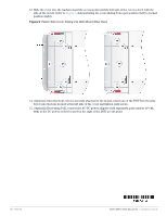
13. Slide the cover into the tracks toward the access point until the left side of the cover is level with the side of the mount. Refer to Figure 6, demonstrating the cover sliding from open position (left) to locked position (right). Figure 6 Plastic Side Cover Sliding into Wall Mount (Rear View) 14. (Optional) Once the front cover is securely attached to the mount, insert one of the T8H Torx Security Screw into the hole located at the left side of the cover and tighten until secure. 15. (Optional) If not using PoE, connect the AC-DC power adapter (sold separately, part number AP-CBLSER) to the DC power socket located on the right of the 205H access point. 0511763-03 205H-MNT2 Wall Mount Kit | Installation Guide
-
 1
1 -
 2
2 -
 3
3 -
 4
4
 |
 |

0511763-03
205H-MNT2 Wall Mount Kit
|
Installation Guide
13. Slide the cover into the tracks toward the access point until the left side of the cover is level with the
side of the mount. Refer to
Figure 6
, demonstrating the cover sliding from open position (left) to locked
position (right).
Figure 6
Plastic Side Cover Sliding into Wall Mount (Rear View)
14. (Optional) Once the front cover is securely attached to the mount, insert one of the T8H Torx Security
Screw into the hole located at the left side of the cover and tighten until secure.
15. (Optional) If not using PoE, connect the AC-DC power adapter (sold separately, part number
AP-CBL-
SER
) to the DC power socket located on the right of the 205H access point.