Dell XPS 15 9500 Service Manual
Dell XPS 15 9500 Manual
 |
View all Dell XPS 15 9500 manuals
Add to My Manuals
Save this manual to your list of manuals |
Dell XPS 15 9500 manual content summary:
- Dell XPS 15 9500 | Service Manual - Page 1
XPS 15 9500 Service Manual Regulatory Model: P91F Regulatory Type: P91F001 June 2020 Rev. A01 - Dell XPS 15 9500 | Service Manual - Page 2
of data and tells you how to avoid the problem. WARNING: A WARNING indicates a potential for property damage, personal injury, or death. © 2020 Dell Inc. or its subsidiaries. All rights reserved. Dell, EMC, and other trademarks are trademarks of Dell Inc. or its subsidiaries. Other trademarks may be - Dell XPS 15 9500 | Service Manual - Page 3
Safety instructions...5 Electrostatic discharge-ESD protection...6 ESD field service kit ...6 Transporting sensitive components...7 After working inside your computer...7 Chapter 2: Removing and installing components 8 Recommended tools...8 Screw list...8 Major components of XPS-15 9500...9 Base - Dell XPS 15 9500 | Service Manual - Page 4
CMOS settings...58 Clearing BIOS (System Setup) and System passwords 58 Chapter 5: Troubleshooting...60 SupportAssist diagnostics...60 Built-in self-test (BIST)...60 System board built-in 65 WiFi power cycle...65 Flea power release...65 Chapter 6: Getting help and contacting Dell 66 4 Contents - Dell XPS 15 9500 | Service Manual - Page 5
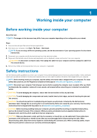
and the contacts. CAUTION: You should only perform troubleshooting and repairs as authorized or directed by the Dell technical assistance team. Damage due to servicing that is not authorized by Dell is not covered by your warranty. See the safety instructions that is shipped with the product or at - Dell XPS 15 9500 | Service Manual - Page 6
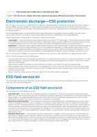
obvious, such as intermittent problems or a shortened product life span. As the industry pushes difficult type of damage to recognize and troubleshoot is the intermittent (also called latent or between your skin, the ESD mat, and the hardware is known as bonding. Use only Field Service kits with - Dell XPS 15 9500 | Service Manual - Page 7
for safe transport. ESD protection summary It is recommended that all field service technicians use the traditional wired ESD grounding wrist strap and protective anti-static mat at all times when servicing Dell products. In addition, it is critical that technicians keep sensitive parts separate - Dell XPS 15 9500 | Service Manual - Page 8
1. Screw list Component Base cover Secured to Palm-rest and keyboard assembly Screw type M2x3 Quantity 8 Screw image Battery Palm-rest and M2x3 4 keyboard assembly Battery Palm-rest and M2x4 4 keyboard assembly Right fan System board and M2x4 1 palm-rest and keyboard assembly - Dell XPS 15 9500 | Service Manual - Page 9
Touchpad Touchpad Palm-rest and M2x4 2 keyboard assembly Palm-rest and M1.6x2.5 4 keyboard assembly Palm-rest and M2x2 4 keyboard assembly Major components of XPS-15 9500 The following image shows the major components of XPS-15 9500. Screw image Removing and installing components 9 - Dell XPS 15 9500 | Service Manual - Page 10
1. Base cover 2. Battery 3. Heat sink 4. Memory module 5. Right fan 6. USB Type-C bracket 7. System board 8. Graphics card-processor thermal bracket 9. Speaker 10. Display assembly 11. Palm-rest and keyboard assembly 12. Wireless-card bracket 13. I/O-board shield 14. I/O board 15. USB Type-C port - Dell XPS 15 9500 | Service Manual - Page 11
for the original system configuration purchased. These parts are available according to warranty coverages purchased by the customer. Contact your Dell sales representative for purchase options. Base cover Removing the base cover Prerequisites 1. Follow the procedure in Before working inside your - Dell XPS 15 9500 | Service Manual - Page 12
12 Removing and installing components - Dell XPS 15 9500 | Service Manual - Page 13
damage to the pins. 2. Starting from the bottom-left corner, use a plastic scribe to pry the base cover in the direction of the arrows to release the base cover from the palm-rest and keyboard assembly. 3. Grasp the left side and the right side of the base cover and remove the - Dell XPS 15 9500 | Service Manual - Page 14
BIOS when this error appears and set the date and time on your computer to resume normal functionality. 4. Disconnect the battery cable from the system board. 5. Turn your computer over and press the power button for 15 seconds to drain - Dell XPS 15 9500 | Service Manual - Page 15
Steps 1. Connect the battery cable to the system board, if applicable. 2. Align the error appears and set the date and time on your computer to resume normal functionality. 1. Follow the procedure in After working inside your computer. Battery Lithium-ion battery precautions CAUTION: • Exercise - Dell XPS 15 9500 | Service Manual - Page 16
, do not try to release it as puncturing, bending, or crushing a lithium-ion battery can be dangerous. In such an instance, contact Dell technical support for assistance. See www.dell.com/contactdell. • Always purchase genuine batteries from www.dell.com or authorized Dell partners and resellers - Dell XPS 15 9500 | Service Manual - Page 17
to the palm-rest and keyboard assembly. 4. Replace the four screws (M2x4) that secure the battery to the palm-rest and keyboard assembly. 5. Connect the battery cable to the system board. Next steps 1. Install the base cover. 2. Follow the procedure in After working inside your computer. Memory - Dell XPS 15 9500 | Service Manual - Page 18
About this task The following image indicates the location of the memory modules and provides a visual representation of the removal procedure. Steps 1. Use your fingertips to carefully spread apart the securing-clips on each end of the memory-module slot until the memory module pops up. 2. Slide - Dell XPS 15 9500 | Service Manual - Page 19
Steps 1. Align the notch on the memory module with the tab on the memory-module slot. 2. Slide the memory module firmly at an angle, into the memory-module slot. 3. Press the memory module down until it clicks into place. NOTE: If you do not hear the click, remove the memory module and reinstall it. - Dell XPS 15 9500 | Service Manual - Page 20
Steps 1. Remove the screw (M2x2) that secures the solid-state drive thermal bracket and the solid-state drive1 to the system board. 2. Slide the solid-state drive thermal bracket from the alignment post and lift it from the system board. 3. Slide and remove the solid-state drive1 from the solid- - Dell XPS 15 9500 | Service Manual - Page 21
Steps 1. Align the notch on the solid-state drive1 with the tab on the solid-state drive slot. 2. Gently slide the solid-state drive1 into the solid-state drive slot. 3. Slide the solid-state drive thermal bracket into the alignment post on the system board. 4. Align the screw hole on the solid- - Dell XPS 15 9500 | Service Manual - Page 22
before performing the installation procedure. CAUTION: Solid-state drives are fragile. Exercise care when handling the solid-state drive. NOTE: Your computer supports 2 solid-state drive slots. Solid-state drive1 is the primary slot and solid-state drive2 is the secondary slot. If you are installing - Dell XPS 15 9500 | Service Manual - Page 23
drive Prerequisites If you are replacing a component, remove the existing component before performing the installation procedure. About this task This computer supports two solid-state drive form factors. • M.2 2230 • M.2 2280 If you are replacing the M.2 2280 solid-state drive with an M.2 2230 - Dell XPS 15 9500 | Service Manual - Page 24
2. Secure the M.2 2230 solid-state drive to the bracket with a M2x2 screw. 3. To install the M.2 2230 solid-state drive card to the solid-state drive card slot1, see installing the solid state drive1. To install the M.2 2230 solid-state drive card to the solid-state drive card slot2, see installing - Dell XPS 15 9500 | Service Manual - Page 25
Steps 1. Disconnect the fan cable from the system board. 2. Remove the two screws (M2x4) that secure the fan to the system board and palm-rest and keyboard assembly. CAUTION: Do not hold the fan assembly at the center, as it may damage the center bearing. 3. Slide the fan out of the heat sink and - Dell XPS 15 9500 | Service Manual - Page 26
Steps 1. Connect the fan cable to the system board. 2. Slide fan below the heat sink and align the screw holes on fan with the screw holes on the system board and palm-rest and keyboard assembly. 3. Replace the two screws (M2x4) that secure the fan to the system board and palm-rest and keyboard - Dell XPS 15 9500 | Service Manual - Page 27
Steps 1. Remove the two screws (M2x4) that secure the I/O-board shield to the fan and palm-rest and keyboard assembly. 2. Lift the I/O-board shield off the system board. 3. Remove the screw (M2x4) that secures the fan to the system board. 4. Disconnect the fan cable from the system board. CAUTION: - Dell XPS 15 9500 | Service Manual - Page 28
inside your computer. CAUTION: For maximum cooling of the processor, do not touch the heat transfer areas on the heat sink. The oils in your skin can reduce the heat transfer capability of the thermal grease. NOTE: The heat sink may become hot during normal operation. Allow sufficient time for the - Dell XPS 15 9500 | Service Manual - Page 29
Steps 1. In reverse sequential order (as indicated on the heat sink), loosen the four captive screws that secure the heat sink to the system board. 2. Lift the heat sink off the system board. Installing the heat sink Prerequisites If you are replacing a component, remove the existing component - Dell XPS 15 9500 | Service Manual - Page 30
Steps 1. Align the screw holes on the heat sink with the screw holes on the system board. 2. In sequential order (as indicated on the heat sink), tighten the four captive screws that secure the heat sink to the system board. Next steps 1. Install the base cover. 2. Follow the procedure in After - Dell XPS 15 9500 | Service Manual - Page 31
system board. 2. Peel the tapes that secure the speaker cable to the battery. 3. Remove the two screws (M2x2) that secure the speakers to the palm Note the speaker cable routing, and remove the speaker cable from the routing guides on the palm-rest and keyboard assembly. 5. Lift the speakers, along - Dell XPS 15 9500 | Service Manual - Page 32
the slots of the palm-rest and keyboard assembly. 2. Route the speaker cable through the routing guides on the palm-rest and keyboard assembly. 3. Adhere the tapes that secure the speaker cable to the battery. 4. Replace the two screws (M2x2) that secures the speakers to the palm-rest and keyboard - Dell XPS 15 9500 | Service Manual - Page 33
Steps 1. Disconnect the I/O-board cable from the system board and I/O board. 2. Lift the I/O-board cable from the system board. 3. Disconnect the screw (M2x4) that secures the USB Type-C port bracket to the system board and lift the bracket off the I/O board. 4. Lift the I/O board off the palm-rest - Dell XPS 15 9500 | Service Manual - Page 34
Steps 1. Place the I/O board on the palm-rest and keyboard assembly. 2. Align the screw hole on the USB Type-C port bracket with the screw hole on the system board. 3. Connect the screw (M2x4) that secures the USB Type-C port bracket to the system board. NOTE: Ensure to connect IO marked side of the - Dell XPS 15 9500 | Service Manual - Page 35
Removing and installing components 35 - Dell XPS 15 9500 | Service Manual - Page 36
Steps 1. Loosen the three captive screws that secure the display-assembly cable bracket to the system board. 2. Lift the display-assembly cable bracket off the system board. 3. Remove the two screws (M1.6x3) that secure the display-assembly cable holder to the palm-rest and keyboard assembly. 4. - Dell XPS 15 9500 | Service Manual - Page 37
Removing and installing components 37 - Dell XPS 15 9500 | Service Manual - Page 38
Steps 1. Slide the palm-rest and keyboard assembly under the display-assembly hinges. 2. Align the screw holes on the palm-rest assembly with the screw holes on the right and left display-assembly hinges. 3. Replace the four screws (M2.5x5.5) that secure the left hinge to the system board and the - Dell XPS 15 9500 | Service Manual - Page 39
the system board. NOTE: The Service Tag of your computer is stored in the system board. Enter the Service Tag in the BIOS setup program error appears and set the date and time on your computer to resume normal functionality. 2. Remove the base cover. 3. Remove the battery. 4. Remove the speakers. - Dell XPS 15 9500 | Service Manual - Page 40
40 Removing and installing components - Dell XPS 15 9500 | Service Manual - Page 41
If you are replacing a component, remove the existing component before performing the installation procedure. NOTE: The Service Tag of your computer is stored in the system board. Enter the Service Tag in the BIOS setup program after you replace the system board. NOTE: Replacing the system board - Dell XPS 15 9500 | Service Manual - Page 42
restarts several times and then an error message is displayed- "Time of day not set". Enter the BIOS when this error appears and set the date and time on your computer to resume normal functionality. About this task The following image indicates the connectors on your system board. Figure 2. System- - Dell XPS 15 9500 | Service Manual - Page 43
Removing and installing components 43 - Dell XPS 15 9500 | Service Manual - Page 44
14. Connect the touch screen cable and camera cable to the display-assembly cable. 15. Align the screw holes on the display-assembly cable bracket with the screw holes solid state drive1. 7. Install the memory. 8. Install the battery. 9. Install the speakers. 44 Removing and installing components - Dell XPS 15 9500 | Service Manual - Page 45
the palm-rest and keyboard assembly Prerequisites 1. Follow the procedure in Before working inside your computer. 2. Remove the base cover. 3. Remove the battery. 4. Remove the speakers. 5. Remove the memory. 6. Remove the solid state drive1. 7. Remove the solid state drive2. 8. Remove the heat sink - Dell XPS 15 9500 | Service Manual - Page 46
the right fan. 6. Install the heat sink. 7. Install the solid state drive2. 8. Install the solid state drive1. 9. Install the memory. 10. Install the battery. 11. Install the speakers. 12. Install the base cover. 13. Follow the procedure in After working inside your computer. 46 Removing and - Dell XPS 15 9500 | Service Manual - Page 47
3 Drivers and downloads When troubleshooting, downloading or installing drivers it is recommended that you read the Dell Knowledge Based article, Drivers and Downloads FAQ SLN128938. Drivers and downloads 47 - Dell XPS 15 9500 | Service Manual - Page 48
information about the hardware installed in your computer, such as the amount of RAM and the size of the hard drive. • Change the system configuration drive or hard drive). During the Power-on Self Test (POST), when the Dell logo appears, you can: • Access System Setup by pressing F2 key • Bring - Dell XPS 15 9500 | Service Manual - Page 49
menu Overview XPS 15 9500 BIOS Version Displays the BIOS version number. Service Tag Displays the Service Tag of the computer. Asset Tag Displays the Asset Tag of the computer. Manufacture Date Displays the manufacture date of the computer. Ownership Date Displays the ownership date of - Dell XPS 15 9500 | Service Manual - Page 50
Table 3. System setup options-System information menu (continued) Overview Maximum Clock Speed Displays the maximum processor clock speed. Minimum Clock Speed Displays the minimum processor clock speed. Current Clock Speed Displays the current processor clock speed. Core Count Displays the - Dell XPS 15 9500 | Service Manual - Page 51
System Configuration Date/Time Date Time Storage Interface Port Enablement Sets the computer date in MM/DD/YYYY format. Changes to the date take effect drive controller. Default: RAID On. SATA is configured to support RAID (Intel Rapid Restore Technology). Drive Information Enable SMART - Dell XPS 15 9500 | Service Manual - Page 52
options-Video menu Video LCD Brightness Brightness on battery power Sets the screen brightness when the computer is running on battery power. Default: 50 Brightness on AC power of the optional Absolute Persistence Module service from Absolute Software. Default: Enabled 52 System setup - Dell XPS 15 9500 | Service Manual - Page 53
Table 7. System setup options-Security menu (continued) Security TPM 2.0 Security On Select whether or not the Trusted Platform Model (TPM) is visible to the OS. Default: ON PPI Bypass for Enable Commands Enables or disables the OS to skip BIOS Physical Presence Interface (PPI) user prompts - Dell XPS 15 9500 | Service Manual - Page 54
Mode Key Management Selects the custom values for expert key management. Default: PK Table 11. System setup options-Performance menu Performance Multi-Core Support Active Cores Changes the number of CPU cores available to the operating system. The default value is set to the maximum number of - Dell XPS 15 9500 | Service Manual - Page 55
to the computer. Default: OFF Wake on Dell USB-C Dock Enables connecting a Dell USB-C Dock to wake the computer from Standby. Default: ON Battery Charged maximizes battery health while still supporting heavy use during the work day. Default: OFF Peak Shift Enables the computer to run on battery - Dell XPS 15 9500 | Service Manual - Page 56
Shift Technology Enables or disables the Intel Speed Shift Technology support. Setting this option to enable allows the operating system to little power capacity are detected. Default: ON Enable Dock Warning Messages Enables or disables dock warning messages. Default: ON Fastboot Configures the - Dell XPS 15 9500 | Service Manual - Page 57
Life. Default: ON MAC Address Pass-Through Replaces the external NIC MAC address (in a supported dock or dongle) with the selected MAC address from the computer. Default: System Unique MAC Address. Table 15 Asset Tag cannot be changed. Service Tag Displays the Service Tag of the computer. BIOS - Dell XPS 15 9500 | Service Manual - Page 58
BIOSConnect Enables or disables cloud Service OS recover if the main base cover. NOTE: The battery must be disconnected from the system board. Press and hold the power button for 15 seconds to drain the flea power. Dell technical support as described at www.dell.com/contactdell. 58 System setup - Dell XPS 15 9500 | Service Manual - Page 59
NOTE: For information on how to reset Windows or application passwords, refer to the documentation accompanying Windows or your application. System setup 59 - Dell XPS 15 9500 | Service Manual - Page 60
. M-BIST must be manually initiated before POST and Battery LED light with Solid Amber Battery LED error code of [2,8] blinks Amber x2, then pause, then blinks White x8. Repair instruction Indicates a problem with the system board. Indicates a problem with the system board. 60 Troubleshooting - Dell XPS 15 9500 | Service Manual - Page 61
board. 3. Replace the system board to fix the issue. NOTE: The battery status LED will not illuminate if there is no failure present with the system board. If further troubleshooting is required, proceed with the applicable Guided Resolution for No Power/No POST, etc. Display panel power rail built - Dell XPS 15 9500 | Service Manual - Page 62
1. Press and hold the D key and then press the power button. 2. Release both the D key and the power button when the computer begins POST. 3. detected with system board. Solid amber Table 20. BIST outcome Indicates a problem with the system board. L-BIST Off No fault detected with system board - Dell XPS 15 9500 | Service Manual - Page 63
the computer is turned off indicating no memory or RAM is detected. The following table shows different power and battery-status light patterns and associated problems. Table 21. LED codes Diagnostic light codes • Solid white - Camera is in use. • Off - Camera is not in use. Troubleshooting 63 - Dell XPS 15 9500 | Service Manual - Page 64
website to troubleshoot and fix your computer when it fails to boot into their primary operating system due to software or hardware failures. For more information about the Dell SupportAssist OS Recovery, see Dell SupportAssist OS Recovery User's Guide at www.dell.com/ support. Flashing the BIOS - Dell XPS 15 9500 | Service Manual - Page 65
troubleshoot and fix problems that may occur with Windows. Dell proposes multiple options for recovering Windows operating system on your Dell PC. For more information. see Dell battery has been disconnected from the system board. The following procedure provides the instructions on how to release - Dell XPS 15 9500 | Service Manual - Page 66
Self-help resources Self-help resources Information about Dell products and services Resource location www.dell.com My Dell Tips Contact Support Online help for operating system Troubleshooting information, user manuals, set up instructions, product specifications, technical help blogs, drivers
-
 1
1 -
 2
2 -
 3
3 -
 4
4 -
 5
5 -
 6
6 -
 7
7 -
8
-
9
-
10
-
11
-
12
-
13
-
14
-
15
-
16
-
17
-
18
-
19
-
20
-
21
-
22
-
23
-
24
-
25
-
26
-
27
-
28
-
29
-
30
-
31
-
32
-
33
-
34
-
35
-
36
-
37
-
38
-
39
-
40
-
41
-
42
-
43
-
44
-
45
-
46
-
47
-
48
-
49
-
50
-
51
-
52
-
53
-
54
-
55
-
56
-
57
-
58
-
59
-
60
-
61
-
62
-
63
-
64
-
65
-
66
 |
 |

XPS 15 9500
Service Manual
Regulatory Model: P91F
Regulatory Type: P91F001
June 2020
Rev. A01